Metal damper and design method thereof

A technology of metal dampers and dampers, which is applied in bridge construction, bridge parts, bridges, etc., can solve the problems of poor lateral deformation capacity and fatigue resistance of dampers, which affect design and use, and achieve strong design and use Convenience, flexibility, and strong applicability

Active Publication Date: 2013-11-20
TSINGHUA UNIV
View PDF5 Cites 16 Cited by
  • Summary
  • Abstract
  • Description
  • Claims
  • Application Information

AI Technical Summary

Problems solved by technology

Therefore, both theoretical and experimental verifications show that the above-mentioned dampers have poor lateral deformati

Method used


Image

  • Metal damper and design method thereof
  • Metal damper and design method thereof
  • Metal damper and design method thereof

Examples


Embodiment 1

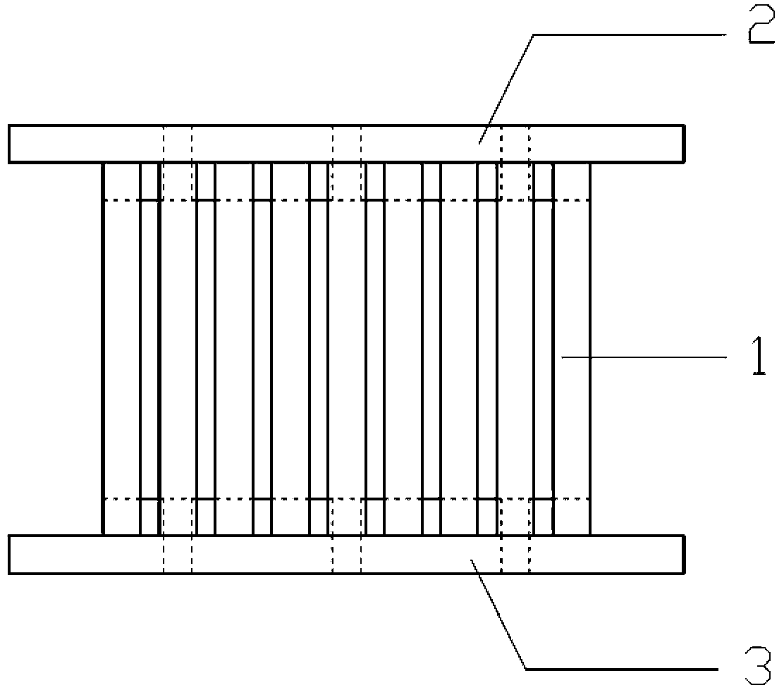
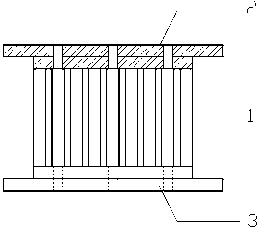
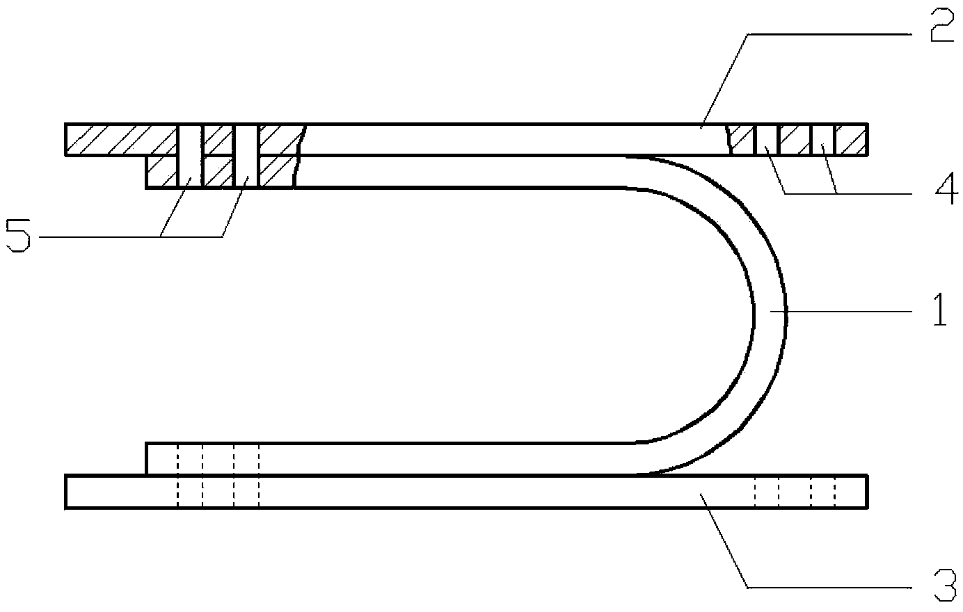
[0040] Such as figure 1 , figure 2 , image 3 The metal damper shown includes a core metal energy dissipation element, an upper cover plate 2 and a lower cover plate 3. The core metal energy dissipation element is a continuous U-shaped slotted metal plate 1 that is bent and deformed by rolling.

[0041] Such as Figure 4 and Figure 5 As shown, the slotted metal plate 1 is composed of an arc segment 6 and a straight segment 7, and a part of the arc segment 6 and the straight segment 7 are continuously slotted at equal intervals along the width direction; the ungrooved part of the straight segment 7 is provided with bolts hole; such as Figure 6 As shown, the through hole 5 at one end of the upper and lower cover plates is fixedly connected with the slotted metal plate 1 and the building structure at the same time, and the bolt hole 4 opened at the other end is only fixedly connected with the building structure.

[0042] During installation, the slotting direction of the ...

Embodiment 2

[0057] Such as Figure 9 and Figure 10 As shown, this example is similar to the first example, except that the arrangement direction of the metal dampers in this example is perpendicular to that in the first example.

[0058] In fact, the performance of the metal damper is quite stable in all directions. In actual installation, it can be installed arbitrarily according to the requirements of various building structures, and the installation direction can be flexibly designed.

Embodiment 3

[0060] When used for energy dissipation and shock absorption of bridge structures, such as Figure 11 , Figure 12 As shown, the metal damper of the present invention is placed between the bridge body and the bridge pier, and used in parallel with the bridge body support, and the threaded holes provided on the upper cover plate 2 and the lower cover plate 3 of the metal damper of the present invention are used. Fasteners (conventional technical methods, not specifically shown in the figures) connect the present invention with the bridge body and the bridge pier respectively. When connecting, the slotting direction of the metal plate can be parallel or perpendicular to the length direction of the bridge body, Figure 11 and Figure 12 Draw a schematic diagram of the installation when the slotting direction of the slotted metal plate is parallel to the length direction of the bridge body, Figure 13 and Figure 14 A schematic diagram of installation when the width of the slo...


PUM


Abstract

The invention provides a metal damper and a design method thereof, and belongs to the technical field of civil engineering structural shock absorption. The damper comprises an upper cover plate, a lower cover plate and a core energy-consuming metal element. The core energy-consuming metal element is a continuous U-shaped slotted metal plate and comprises a circular arc section and two straight sections. A plurality of continuous grooves are formed in the circular arc section and partial straight sections of the slotted metal plate in the width direction at intervals. In design, firstly, the height of the damper is determined according to a building; secondly, the numerical relationship of the thickness of a steel plate, the length of the straight sections and the width of the damper is obtained according to an in-plane resilience formula and an out-plane resilience formula; specific numerical values of the three parameters are adjusted according to an optimizing formula, so that a failure mode, out of expectation, of the damper does not occur; and ultimately, the number of the dampers and the size of a bolt are determined. According to the metal damper and the design method of the metal damper, energy consumption is achieved through metal materials with strong plastic deformation capacity, large longitudinal deformation is achieved through bending deformation, and large sideward deformability and anti-fatigue performance are achieved.

Description

technical field [0001] The invention belongs to the technical field of shock absorption of civil engineering structures, and in particular relates to a metal damper arranged between a bridge pier and a beam slab or a metal damper in a building structure in bridge engineering and a design method thereof. Background technique [0002] The development of today's buildings tends to be more and more tall, and the frame structure composed of steel members, composite members or reinforced concrete members is a structural form that is often used in buildings. In order to make the building structure have a strong ability to resist damage from external forces such as earthquakes or wind loads, it is often necessary to add metal energy-dissipating components to the frame structure. The development of bridge engineering tends to be more and more large-scale. In order to ensure the safety of bridge structures during earthquakes and prevent bridge falls, rubber vibration isolation pads ar...

Claims


Application Information

Patent Timeline
IPC IPC(8): E01D19/04E04B1/98
Inventor 潘鹏陈浩文邓开来
Owner TSINGHUA UNIV
Why Eureka
Try Eureka