Rotary low-damping energy-saving drained water splash device

A splash device and low damping technology, which is applied in the field of rotary falling water splash device, can solve the problems of centrifugal splash device, such as short service life, affecting the rotation flexibility of the runner, and difficult to guarantee the reliability of use, so as to reduce The number of production molds is conducive to manufacturing and the effect of uniform size

Inactive Publication Date: 2013-11-20
常州金坛塑料厂
View PDF1 Cites 2 Cited by
  • Summary
  • Abstract
  • Description
  • Claims
  • Application Information

AI Technical Summary

Problems solved by technology

[0003] Although this centrifugal high-efficiency splashing device has the above-mentioned advantages, there are still the following disadvantages in the actual use process: the runner is rotatably installed on the support frame through the splashing dish, and the mandrel at the lower end of the running wheel and the splashing dish is Gap set structure, if the gap is too small, it will not only affect the rotation flexibility of the runner, but also increase the friction resistance, if the gap is too large, the runner will swing during the rotation process, and at the same time, it will also accelerate the friction between the two, shortening the service life , when the matching gap between the two is out of tolerance, the runner will be stuck and cannot rotate, which will cause the centrifugal splash device to fail. Once this happens, it cannot be repaired, and it must only be replaced as a whole, and the workload is heavy. , Practice has proved that the service life of such a centrifugal splash device is not long, the workload of maintenance and replacement is very large, and the reliability of use is difficult to guarantee

Method used


Image

  • Rotary low-damping energy-saving drained water splash device
  • Rotary low-damping energy-saving drained water splash device
  • Rotary low-damping energy-saving drained water splash device

Examples


Embodiment 1

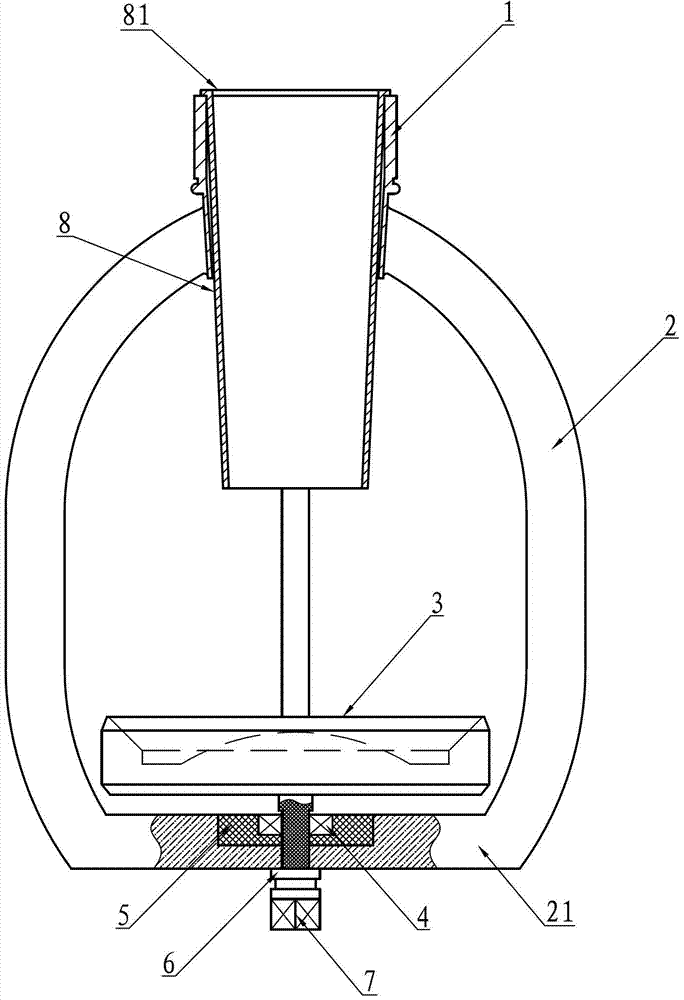
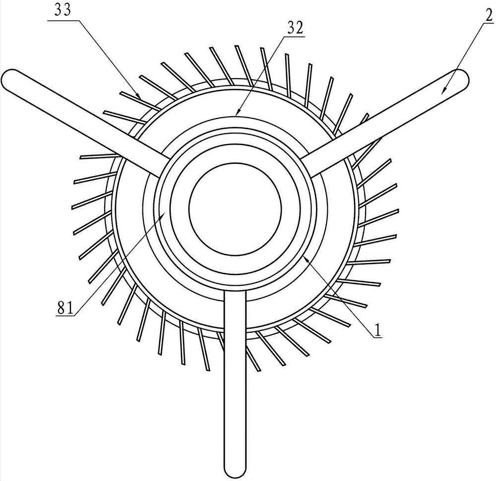
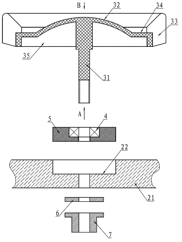
[0021] A rotary low-damping energy-saving falling water splashing device, such as Figure 1~5 As shown: including connecting pipe 1, three-rib support frame 2, splashing water disc 3, rolling bearing 4, bearing seat 5, washer 6, fastening nut 7 and nozzle sleeve 8, the three ribs of the support frame 2 The upper end is evenly fixed on the lower part of the connecting pipe 1, and the lower ends of the three ribs converge into a seat body 21, and a mounting hole 22 is provided on the seat body 21; a conjoined rotating shaft 31 is provided at the center of the lower end of the splashing water rotating disc 3, so that the splashing water The upper end surface of the water rotating dish 3 is a protruding water splashing spherical surface 32, and guide fins 33 with radial angles are evenly arranged on the peripheral edge of the water splashing rotating dish 3, and the guiding fins 33 extend to the splashing water spherical surface 32, adjacent to each other. A water-dividing groove ...


PUM


Abstract

The invention discloses a rotary low-damping energy-saving drained water splash device which comprises a connecting pipe, a support frame, a water splash rotary disc and a rolling bearing. The support frame is fixedly arranged on the lower portion of the connecting pipe, a connection rotary shaft is arranged in the center of the lower end of the water splash rotary disc, the upper end surface of the water splash rotary disc is a protruded water splash spherical surface, guide fins are uniformly distributed at the circumferential edge of the water splash rotary disc, radial included angles are formed among the guide fins, and the guide fins extend onto the water splash spherical surface to form water distributing grooves; a base is arranged at the bottom of the support frame, a mounting hole is formed in the center of the base, and the water splash rotary disc is freely rotatably mounted in the mounting hole in the base via the connection rotary shaft and the rolling bearing. The rotary low-damping energy-saving drained water splash device with the structure has the advantages that the rotary low-damping energy-saving drained water splash device is good in stability, the fins at the circumferential edge of the water splash rotary disc are not easy to break and cannot be blocked or skewed during running, a hollowness phenomenon is prevented when the fins run, the rotary low-damping energy-saving drained water splash device is quite suitable for a water distribution system of a natural draft cooling tower, and the long-term efficient and economic running ability of the cooling tower can be greatly improved.

Description

Technical field: [0001] The invention relates to a falling water splashing device used in a cooling tower, in particular, a rotating falling water splashing device is designed. Background technique: [0002] The function of the cooling tower is to exchange heat between the cooling water and the air in the tower, so that the waste heat is transferred to the air and scattered into the atmosphere. The working principle of the cooling tower is that the circulating water with a certain temperature flowing out of the condenser is passed through the pipe through the shaft into the hot water distribution system. This distribution system is arranged in a net shape on the plane, and the water distribution is divided into grooves, pipes or grooves and pipes. It falls into the reservoir in the form of rain, and the cold air enters the tower body from the air inlet, passes through the rain area under the water filling, and forms convective heat exchange with the hot water rain flow, pas...

Claims


Application Information

Patent Timeline
Patent Type & Authority Applications(China)
IPC IPC(8): F28F25/06
Inventor 李罗中俞斌
Owner 常州金坛塑料厂
Why Eureka
Try Eureka