[0036] In order to make the object, technical solution and advantages of the present invention more clear and definite, the present invention will be further described in detail below with reference to the accompanying drawings and examples.
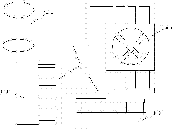
[0037] The invention discloses a magnetocaloric system, which converts thermal energy of a heat source at 20°C to 200°C into mechanical energy, such as figure 1 As shown, it includes a thermal energy collection device 1000 for collecting thermal energy, a thermal energy transmission device 2000 for transmitting thermal energy, a magnetothermal engine unit 3000 for converting thermal energy into mechanical energy output, and a cooling system 4000 for discharging residual heat; the thermal energy collection device 1000 and the magnetothermal engine The unit 3000 is connected through the thermal energy transmission device 2000, and the magneto-thermal engine unit 3000 and the cooling system 4000 are connected through the thermal energy transmission device 2000;
[0038] The magneto-thermal engine unit 3000 includes at least one magneto-thermal engine unit 3100 that converts thermal energy into mechanical energy and a power shaft 3200 connected to the magneto-thermal machine unit 3100 , and the magneto-thermal machine unit 3100 drives the power shaft 3200 to rotate. In practical applications, multiple power shafts 3200 can be provided, and the length of the power shafts 3200 can be extended by interconnecting, or multiple power shafts can be arranged side by side, and each power shaft 3200 is provided with at least one magneto-thermal engine unit 3100 . The different power shafts 3200 are connected to the generator through the gear set and the transmission device, and the rotation of the power shaft 3200 drives the generator to generate electricity.
[0039] like figure 2 and image 3As shown, the magneto-thermal engine unit 3100 includes at least two structural units arranged side by side and working together. The structural unit includes a stator structure 3110 whose paramagnetic properties change repeatedly with temperature changes and a stator structure 3110 that cooperates with the stator structure and converts magnetic energy into mechanical energy. Rotor structure 3120, the rotor structure 3120 is symmetrically arranged on both sides of the stator structure 3110; the structural unit also includes a plastic base 3130 for fixing the stator structure 3110; the power shaft 3200 passes through the stator structure 3110 and the rotor structure 3120: the magnetic properties of the stator structure 3110 It changes repeatedly with the temperature change, and then uses the repeated magnetic changes (magnetic energy) of the stator structure 3110 to drive the rotor structure 3120 to rotate, and the rotation of the rotor structure 3120 drives the power shaft 3200 to rotate. In practical applications, the power shaft 3200 is externally connected to some equipment that requires mechanical energy. For example generators. In this embodiment, the magneto-thermal engine unit 3100 includes two structural units, and the two structural units cooperate to drive the power shaft 3200 to rotate.
[0040] The structural unit also includes a sleeve 3140 that is socketed with the power shaft 3200, and the sleeve 3140 is fixedly connected to each rotor structure 3120 in the same magneto-thermal engine unit 3100; the sleeve 3140 is fixedly connected to two adjacent structural units , The shaft sleeve 3140 is tubular, with a keyway structure on its surface, which is convenient for the staff to install, and at the same time increases friction during the rotation process, and is not easy to slip. The power shaft 3200 passes through the stator structure 3110 and the rotor structure 3120 at the same time, and connects multiple magneto-thermal engine units 3100 in series. At the same time, the power shaft 3200 is sleeved with a sleeve 3140, which is fixedly connected to the rotor structure 3120. In one magneto-thermal engine unit 3100 , the shaft sleeve 3140 is fixedly connected with each rotor structure 3120 . A plurality of magneto-thermal engine units 3100 are connected in series, and the rotor structure 3120 in the structural unit of each magneto-thermal engine unit 3100 drives the shaft sleeve 3140 to rotate, thereby driving the power shaft 3200 to rotate and perform work externally. In practical applications, a one-way bearing (not shown in the figure) is provided between the power shaft 3200 and the shaft sleeve 3140: since the power shaft 3200 is connected to multiple magneto-thermal engine units 3100, the structural units in each magneto-thermal engine unit 3100 The rotor structure 3120 drives the power shaft 3200 to rotate. When one of the rotor structures 3120 on the same power shaft 3200 stops rotating, it will easily affect (resistance) the rotation of the power shaft 3200. At this time, the power shaft 3200 and the shaft A one-way bearing is arranged between the sleeves 3140, which can completely avoid the adverse effect that the rotor structure 3120 stops rotating and hinders the power shaft 3200 (the principle is similar to the flywheel in a multi-person bicycle).
[0041] like image 3 As shown, the stator structure 3110 includes a stator 3111, a heat conductor 3112 and a refrigerator 3115; the stator 3111, the heat conductor 3112 and the refrigerator 3115 are respectively fixed on a plastic base 3130 (see figure 2 );
[0042] Among them, the stator 3111 includes a stator shell 3101 and at least two temperature-sensitive soft magnets 3102 arranged inside the stator shell. The stator shell 3101 is arranged in a disc shape with a hollow interior. 3102 is the same, fixedly placed the soft magnetic fixed cavity of temperature-sensitive soft magnetic, the soft magnetic fixed cavity is arranged evenly and symmetrically; the power shaft 3200 and the sleeve pass through the center of the stator 3111; in this embodiment, 4 are set in one structural unit Temperature sensitive soft magnetic 3102 (see image 3 and Figure 5 ), each temperature-sensitive soft magnetic 3102 is fan-shaped and fixed evenly and symmetrically inside the stator shell. The temperature-sensitive soft magnetic 3102 is sensitive to temperature. When the temperature rises to the Curie temperature of the temperature-sensitive soft magnetic 3102, the temperature-sensitive soft magnetic 3102 loses its magnetism. When the temperature drops below the Curie temperature of the temperature-sensitive soft magnetic 3102, the temperature-sensitive soft The temperature-sensitive soft magnet 3102 restores its magnetism, and the rotation of the rotor structure 3120 is controlled through the change of the magnetism of the temperature-sensitive soft magnet 3102, thereby driving the power shaft 3200 to rotate.
[0043] The heat conductor 3112 and the refrigerator 3115 are respectively arranged symmetrically on both sides of the arc surface of the stator 3111 (see image 3 and Figure 5 ), alternately control the temperature of the temperature-sensitive soft magnet, and the horizontal position of the refrigerator 3115 is higher than that of the heat conductor 3112, which is conducive to the full circulation of the heat-conducting material during heat energy transfer and improves the heat energy exchange efficiency. The heat conductor 3112 is connected to the heat collection device 1000 through the heat transfer device 2000, and the refrigerator 3115 is connected to the cooling system 4000 through the heat transfer device 2000 (see figure 2 ), the heat conductor 3112 transfers the heat in the heat collection device 1000 to the temperature-sensitive soft magnet 3102 inside the stator shell 3101, and the refrigerator 3115 discharges the heat of the temperature-sensitive soft magnet 3102 to the heat dissipation system 4000, specifically, in the heat energy transmission device The end heat pipe 2300 is installed at the connection between the 2000 and the heat conductor 3112, and the end cooling pipe 4100 is arranged at the connection between the heat dissipation system 4000 and the refrigerator 3115. The shape and structure of the end heat pipe 2300 and the end cooling pipe 4100 are the same, both of which are in the shape of a rectangular parallelepiped pipe. , the end heat pipe 2300 and the end cooling pipe 4100 are vacuumed inside and filled with vacuum superconducting fluid. The plane area of the end heat pipe 2300 in contact with the heat conductor 3112 is larger than other surfaces (increasing the contact area can improve heat conduction efficiency), and the end cooling The plane area of the tube 4100 in contact with the refrigerator 3115 is larger than other surfaces (increasing the contact area can improve the heat dissipation efficiency), and this arrangement can effectively improve the transfer of heat energy, thereby improving the conversion efficiency of heat energy. In practical application, the end heat pipe 2300 and the end refrigeration pipe 4100 are connected to the heat conductor 3112 and the refrigerator 3115 in the multiple magneto-thermal machine units 3100 .
[0044] The heat conductor 3112 and the refrigerator 3115 are vacuumed inside and filled with vacuum superconducting liquid; the heat conductor 3112 is provided with a heat conduction pipe 3113, and the two ends of the heat conduction pipe 3113 are respectively connected to the top and bottom of the heat conductor 3112, and a section of the heat conduction pipe 3112 is fixedly arranged on In the gap between two adjacent soft magnetic fixed cavities inside the stator housing 3101 (see Figure 5 ), a heat conduction valve 3114 is provided at the connection between the heat conduction pipe 3113 and the bottom of the heat conduction pipe 3112; Since a section of the heat conduction pipe 3112 is fixedly arranged in the gap between two adjacent soft magnetic fixed cavities inside the stator housing 3101, the vacuum superconducting liquid inside the heat conductor 3112 is affected by the heat transferred from the end heat pipe 2300, and the vacuum The superconducting liquid evaporates into steam, and the steam moves upwards and enters the interior of the stator housing 3101 along the upper heat conduction pipe 3113. The steam transfers heat with the temperature-sensitive soft magnet 3102 inside the stator housing 3101 through the heat-conduction pipe 3113, and the temperature of the temperature-sensitive soft magnet 3102 rises. High, the temperature of the steam drops and turns into a vacuum superconducting liquid again. When the heat conducting valve 3114 at the lower end of the heat conducting pipe 3113 is opened, the vacuum superconducting liquid flows out along the heat conducting pipe 3113 and flows into the heat conductor 3112 to form a circulation; the heat conduction pipe 3112 Heat exchange is performed with the temperature-sensitive soft magnet 3102 inside the stator housing 3101 through the circulation of the vacuum superconducting liquid.
[0045] The refrigerator 3115 is provided with a refrigeration pipeline 3116, the two ends of the refrigeration pipeline 3116 are respectively connected to the top and bottom of the refrigerator 3115, and a section of the refrigeration pipeline 3116 is fixedly arranged in the gap between two adjacent soft magnetic fixed cavities inside the stator shell 3101 in (see Figure 5 ), a refrigeration valve 3117 is provided at the connection between the refrigeration pipeline 3116 and the bottom of the refrigerator 3115. The working process of the refrigerator 3115 is the same as that of the heat conductor 3112. Through the conversion of the gas-liquid state of the vacuum superconducting liquid inside the refrigerator 3115, the heat of the temperature-sensitive soft magnetic 3102 is taken away to achieve the cooling effect. At the same time, the heat is transferred to the heat dissipation system 4000 through the terminal cooling pipeline 4100 for processing.
[0046] In order to improve the heat transfer efficiency inside the stator, the stator housing 3101 is filled with a porous foam-like heat-conducting material (not shown in the figure). The heat-conducting material of the porous foam-like structure can be aluminum foam or copper foam. The heat-conducting material with a foam structure can achieve the effect of rapid heat transfer, and realize the rapid change of the temperature of the temperature-sensitive soft magnetic 3102, which is conducive to improving the efficiency of the entire magnetic-thermal system.
[0047] The plastic base 3130 is provided with a circular cavity for fixing the stator 3111, and on both sides of the circular cavity are provided with a heat conductor fixing cavity and a refrigerator fixing cavity for respectively fixing the heat conductor 3112 and the refrigerator 3115, and the plastic base 3130 On the one hand, it can protect the stator structure, on the other hand, it can have the effect of heat preservation, reduce heat loss, and improve the efficiency of the magneto-thermal system. In practical applications, the outer surface of the plastic base 3130 is provided with a plurality of protruding blocks 3131 or recessed cavities fitted with the protruding blocks 3131, and these protruding blocks 3131 and recessed cavities can be fitted to fix adjacent magneto-thermal units 3100, it is convenient for the staff to build a large-scale magnetic heating system.
[0048] The rotor structure 3120 includes two rotor bases 3121 symmetrically arranged on both sides of the circular plane of the stator housing 3102, and the number of hard magnets 3122 installed on the rotor bases 3121 is the same as that of the temperature-sensitive soft magnets. The seat 3121 is set in a disc shape, and the circular surface of the rotor base 3121 facing the stator shell 3101 is evenly and symmetrically provided with hard magnetic fixed cavities 3124 having the same number as the soft magnetic fixed cavities. In the magnetic fixing cavity 3124, the hard magnet 3122 and the temperature-sensitive soft magnet 3101 work together; the power shaft 3200 and the bushing 3140 pass through the center of the rotor base 3121, and the bushing 3140 is fixedly connected to the rotor base 3121.
[0049] Specifically, in the two structural units in the same magneto-thermal engine unit 3100, the temperature-sensitive soft magnets 3102 in the two stator structures 3110 are arranged in alignment, and the hard magnets 3122 in the rotor structure 3120 in one structural unit are aligned with the hard magnets 3122 in the stator structure 3110 The temperature-sensitive soft magnets 3102 are aligned, and the hard magnets 3122 of the rotor structure 3120 and the temperature-sensitive soft magnets 3102 of the stator structure 3110 in another structural unit are staggered. That is to say, the two rotor structures 3120 of the two structural units in the same magneto-thermal engine unit 3100 are completely staggered (staggered by 45°, see figure 2), when one rotor structure 3120 is completely aligned with the stator structure 3110, the other rotor structure 3120 must be completely staggered with the stator structure 3110. In actual work, for the same magneto-thermal engine unit 3100, the alternate heating and cooling of the two stator structures 3111 of the magneto-thermal engine unit 3100 is controlled by the heat conduction valve 3114 and the refrigeration valve 3117 (specifically, when the rotor structure 3120 is aligned with the stator structure 3110, The stator structure 3110 in the structural unit corresponding to the rotor structure 3120 starts to be heated, and the other stator structure 3110 starts to be cooled). To put it simply, assuming that the two structural units in the same magneto-thermal engine unit 3100 are structural unit A and structural unit B, in the initial state, the rotor structure 3120A in structural unit A is aligned with the stator structure 3110A, and the rotor structure in structural unit B 3120B and the stator structure 3110B are completely staggered; at this time, the stator structure 3110A is heated (that is, the heat conduction valve 3114A in the structural unit A is opened, and the cooling valve 3117A is closed), at this time, the temperature-sensitive soft magnetic field 3102A in the stator structure 3110A disappears magnetically; at the same time , the stator structure 3110B is refrigerated (that is, the heat conduction valve 3114B in the structural unit B is closed, and the cooling valve 3117B is opened), at this time, the temperature-sensitive soft magnetism 3102B in the stator structure 3110B is magnetically recovered; The magnetic recovery of the soft magnetic 3102B, the temperature sensitive soft magnetic 3102B has an attraction effect (magnetic force) on the hard magnetic 3122B in the rotor structure 3120B, because the rotor structure 3120B is fixed by the shaft sleeve 3140, so the rotor structure 3120B is affected by the temperature sensitive soft magnetic 3102B Under the influence of the magnetic force, it starts to rotate, drives the power shaft 3200 to rotate, and does work until the rotor structure 3120B is aligned with the stator structure 3110B. At this time, the rotor structure 3120A and the stator structure 3110A are completely staggered, and the stator structure 3110B begins to be heated (that is, in the structural unit B The heat conduction valve 3114B of the structure unit A is opened, the refrigeration valve 3117B is closed), the stator structure 3110A starts to be refrigerated (that is, the heat conduction valve 3114A in the structural unit A is closed, and the refrigeration valve 3117A is opened), at this time, the magnetic heat engine unit 3110 completes a cycle, and the two rotors Structures 3120A and 3120B are rotated 45°. After 8 cycles of the magneto-thermal engine unit 3110, the two rotor structures 3120A and 3120B complete a 360° rotation.
[0050] In practical applications, in order to avoid the magnetic interaction between adjacent rotor structures 3120, a magnetic shielding shell (not shown in the figure) is provided on the rotor base 3121 to shield the hard magnetic back 3122 from the temperature-sensitive soft magnetic 3102 side , the magnetic shielding shell does not affect the attraction between the hard magnet 3122 and the temperature-sensitive soft magnet 3102.
[0051] In order to realize the alternate opening and closing of the heat conduction valve 3112 and the refrigeration valve 3115, and to better realize the stable rotation of the rotor structure 3120, a plurality of control heat conduction valves 3112 and refrigeration valves 3115 are evenly and symmetrically arranged on the rotor base 3121. Magnets 3123 ; the resident magnets 3123 are evenly and symmetrically arranged on the circular surface of the rotor base 3121 facing the stator shell 3101 . The resident magnet 3123 is made of cylindrical small-sized permanent magnet material (the quantity of the resident magnet 3123 in a structural unit is determined by the quantity of the temperature-sensitive soft magnet 3102 in the structural unit, generally speaking, the resident magnet 3123 The number is twice the number of temperature-sensitive soft magnets 3102, and in this embodiment, each structural unit is equipped with 8 resident magnets 3123). In practice, in the same magneto-thermal engine unit 3100 , only one structural unit is installed with a resident magnet, and the other structural unit is not installed with a resident magnet. Specifically, there are two ways to arrange the resident magnets: first, 8 resident magnets 3123 are evenly distributed on the outer edge of the rotor base 3121, and the 8 resident magnets 3123 form a radius slightly smaller than the radius of the rotor base 3121. In the circular shape, the magnetic poles of the 8 resident magnets 3123 present a regular interval distribution, that is, the magnetic poles of the two adjacent resident magnets 3123 are opposite; in the second type, 4 resident magnets are evenly distributed on different radii, forming two For a circle with different radii and the same center, the magnetic poles of the resident magnet 3123 do not need to be changed, and the direction of the magnetic poles is not limited. In this embodiment, the first setting mode is adopted (see figure 2 and Figure 4 ). The heat conduction valve 3114 and refrigeration valve 3117 in the present invention adopt magnetically controlled valves or photoelectric signal control valves. When the rotor structure 3120 turns to a specific angle, the resident magnet 3123 opens the corresponding heat conduction valve 3114 or refrigeration valve 3117 to make the heat conductor 3112 or refrigerator 3115 circulates internally to achieve the effect of heat conduction or cooling; or the heat conduction valve 3114 and refrigeration valve 3117 in the present invention can also be controlled by an external control circuit.
[0052] In practical application, at least one positioning magnet (not shown in the figure) cooperating with the resident magnet 3123 is provided on the plastic base 3130, and the resident magnet 3123 cooperates with the locating magnet to position the rotor structure. In this embodiment, a plastic base 3130 is provided with a positioning magnet, and the position of the positioning magnet can be set according to actual needs. In this embodiment, the positioning magnet is inlaid and installed at a specific position of the rotor base 3121. This specific position can be described as: Considering the rotor base 3121 as a clock, the position at 10 minutes after 12 o'clock is the position where the positioning magnet is placed.
[0053] The distance between the positioning magnet and the resident magnet 3123 is adjustable to ensure that the attractive force between them is appropriate. When the rotor structure 3120 rotates to a certain angle, one of the 8 resident magnets 3123 coincides with the positioning magnet and generates an attractive force, thereby producing a tendency to keep the rotor structure 3120 stationary at this position (positioning the rotor structure 3120, At this time, the state of the rotor structure 3120 is the parking state). One of the resident magnets 3123 generates an appropriate force with the positioning magnet, and this force is adjustable, and its magnitude is slightly smaller than the final total attraction of the stator structure 3110 to the rotor structure 3120 when the rotor structure 3120 is in the resident state force (that is to say, when the rotor structure 3120 and the stator structure 3110 are completely staggered, the temperature-sensitive soft magnet 3102 in the stator structure 3110 is refrigerated, and as the temperature of the temperature-sensitive soft magnet 3102 gradually decreases, the temperature-sensitive soft magnet 3102 The attractive force of the magnet 3122 increases gradually, and the rotor structure 3120 leaves the resident state only when the total attractive force of the stator structure 3110 to the rotor structure 3120 reaches the maximum), which ensures that the rotor structure 3120 reaches the maximum when the stator structure 3110 receives the maximum attractive force Only when the positioning magnet is separated from the resident magnet 3123, the rotor structure 3120 rotates, ensuring the maximum conversion efficiency of the magneto-thermal system.
[0054] In the present invention, the resident magnet 3123 also has the role of guiding the rotation of the rotor structure 3120, ensuring that the rotor structure 3120 is guided by an external force (the magnetic force between the resident magnet 3123 and the positioning magnet) at the initial stage of external work, and moves to the preset position. The direction is rotated by a small angle, and this small angle of early rotation ensures that the power shaft 3200 of the entire magneto-thermal system rotates in the same direction, and there will be no reverse rotation of the rotor structure 3120 of a certain structural unit in an accidental state, which improves the present invention. Reliability and safety of magnetocaloric system.
[0055] In practical applications, the thermal energy collection device 1000 includes a plurality of glass vacuum tubes; the glass vacuum tubes are cheap, the production process and processing process are not difficult, the heat collection efficiency is high, and the technical effect of heat collection of more than 95% is realized at a very low cost.
[0056] In practical applications, the heat transfer device 2000 includes a plurality of vacuum thermal superconductors 2100, and the plurality of vacuum thermal superconductors 2100 form a heat transfer pipe, and the inside of the heat transfer pipe is vacuum filled with vacuum superconducting liquid; the heat transfer device 2000 Interlayers are arranged at the junction of every two connected vacuum thermal superconductors 2100 (see Image 6 ). like Image 6 Among them, the junction of the vacuum superconductors 2100A and 2100B is provided with an interlayer 2200, and the junctions between the interlayer 2200 and the vacuum superconductors 2100A and 2100B are respectively provided with a sealing layer 2210 that seals the vacuum superconductors 2100A and 2100B. This arrangement has Disassemble the vacuum superconducting tube by staff: when a certain vacuum superconducting tube 2100 in the thermal energy transmission device 2000 fails, the staff only needs to close the sealing layer 2210 corresponding to the vacuum superconducting tube connected to the two ends of the vacuum superconducting tube, and then The faulty vacuum superconductor can be directly removed; at the same time, when installing, directly connect the new vacuum superconductor, and simultaneously evacuate the air in the interlayer 2200 connected to the two ends of the vacuum superconductor to make the interlayer vacuum and inject a vacuum After the superconducting liquid, the corresponding sealing layer 2200 can be opened. This arrangement avoids the destruction of the internal vacuum of the entire thermal energy transmission device 2000 due to failure of a vacuum superconductor tube that needs to be replaced.
[0057] The heat dissipation system 4000 of the magnetothermal system in the present invention can be a convection tower in actual production, or a large fan, a water tank, etc.; or the heat dissipation system 4000 can also be connected to a waste heat utilization device in the prior art, including a hot water system.
[0058] The present invention adopts temperature-sensitive soft magnet 3102, hard magnet 3122 and power shaft 3200 to work together to realize the technical effect of converting thermal energy into mechanical energy, and has the following advantages:
[0059] 1. Directly convert thermal energy into mechanical energy, and directly drive the rotor of the generator without the use of a steam turbine, with high energy conversion efficiency and low loss.
[0060] 2. In the process of energy conversion, there is no heating of liquid water to vapor state. Since there is no state change of water, there is no absorption of vaporization heat, and the conversion efficiency of the magnetothermal engine is further improved.
[0061] 3. There is no chemical reaction in the energy conversion process, and no material is consumed (only heat energy transfer, temperature change). The magneto-caloric system operates in a fully enclosed manner, which can work stably for decades and has a long service life.
[0062] 4. Using the temperature-sensitive soft magnetic 3102 as the conversion medium, the temperature-sensitive soft magnetic 3102 can withstand a wide range of temperature dynamics, can withstand sharp changes in temperature, and has high reliability; at the same time, the magnetism of the temperature-sensitive soft magnetic 3102 is only affected by temperature, and the outside world The environment has little influence on it, so the magnetocaloric system works stably.
[0063] 5. The temperature-sensitive soft magnetic 3102 has a mature manufacturing process, is easy to produce, and has low cost.
[0064] The invention works in the medium and low temperature (20°C-200°C) region, has low radiation, low construction cost, and is less affected by natural conditions (not affected by natural factors such as sun movement, wind direction and speed), and is especially suitable for large-scale construction. The invention does not pollute the environment during the working process, is green and environmentally friendly, and is suitable for large-scale popularization and application.
[0065] It should be understood that the application of the present invention is not limited to the above examples, and those skilled in the art can make improvements or transformations according to the above descriptions, and all these improvements and transformations should belong to the protection scope of the appended claims of the present invention.