Multi-mode radio frequency antenna switch

An antenna switch, multi-mode radio frequency technology, applied in impedance networks, electrical components, transmission systems, etc., can solve problems such as deterioration of harmonic power suppression capability and insertion loss, reduction of harmonic power suppression capability, and deterioration of insertion loss, etc. Ease the design difficulty, enhance the tolerance, and reduce the effect of insertion loss

Active Publication Date: 2013-11-20
SPREADTRUM COMM (SHANGHAI) CO LTD
View PDF3 Cites 40 Cited by
  • Summary
  • Abstract
  • Description
  • Claims
  • Application Information

AI Technical Summary

Problems solved by technology

Under the action of this high voltage swing, each turn-off branch is equivalent to a nonlinear current source. Therefore, viewed from the radio frequency antenna 105, the radio frequency antenna is equivalent to a rather large nonlinear current source connected in parallel. Under the joint action of linear current source and parasitic capacitance, the harmonic power suppression ability and insertion loss of GSM_TX or DCS_TX are greatly deteriorated
For another example, when one of the UMTS / LTE_TRX branches is working, there is also a nonlinear current source and a large parasitic capacitance between the RF antenna 105 and the ground, which deteriorates the insertion loss of the UMTS / LTE_TRX, narrows the bandwidth and suppresses harmonic power Capacity and linearity indicators IMD2 and IMD3 decline

Method used


Image

  • Multi-mode radio frequency antenna switch
  • Multi-mode radio frequency antenna switch
  • Multi-mode radio frequency antenna switch

Examples


Embodiment Construction

[0027] The following will clearly and completely describe the technical solutions in the embodiments of the present invention with reference to the drawings in the embodiments of the present invention. Apparently, the described embodiments are preferred implementation modes for implementing the present invention, and the description is for the purpose of illustrating the general principle of the present invention, and is not intended to limit the scope of the present invention. The scope of protection of the present invention should be defined by the claims. Based on the embodiments of the present invention, all other embodiments obtained by those of ordinary skill in the art without creative efforts belong to the protection of the present invention. range.

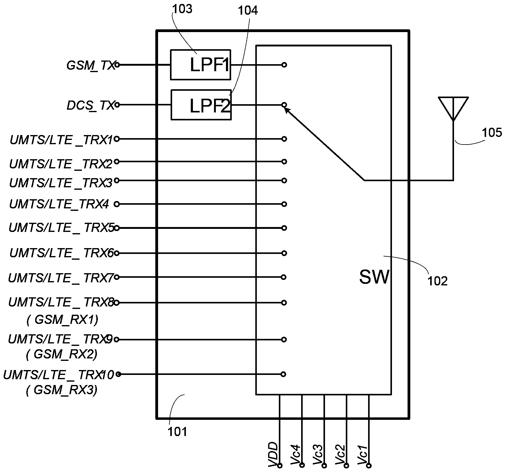
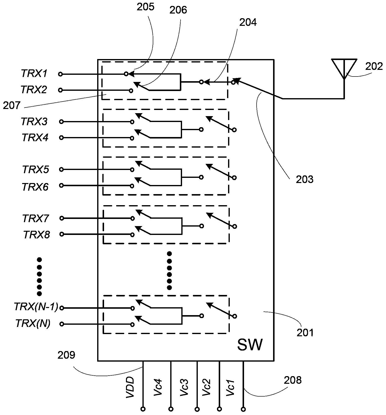
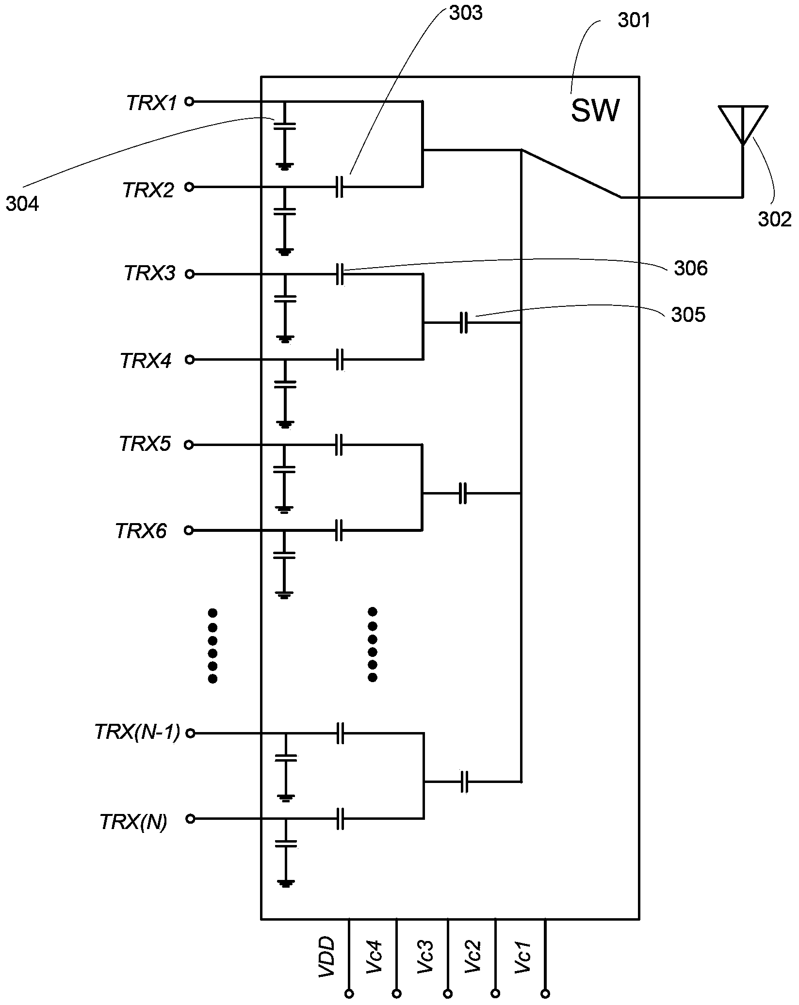
[0028] The existing bus-type RF antenna switch design technology is difficult to apply to multi-mode broadband handheld terminals. A switch with a small number of throws is difficult to cover multiple modes of RF channels...


PUM


Abstract

The invention relates to the field of wireless communication technology and discloses a multi-mode radio frequency antenna switch. The multi-mode radio frequency antenna switch comprises a main switch element, at least one branch switch element, at least one node switch element and at least one branch circuit formed by connecting at least two node switch elements in parallel, wherein all the switch elements form a tree-shaped topological structure, and each node switch element is connected with an emitting/receiving port; each branch circuit is provided with a branch switch element; one end of the main switch element is connected with a radio frequency antenna, and the other end is connected with the branch switch elements in a single-pole multi-throw manner. The multi-mode radio frequency antenna switch adopts the tree-shaped topological structure, not only has a wider frequency band range, but also can effectively reduce parasitic capacitance of the radio frequency antenna to the ground and improve the isolation between the ports, and can achieve a more remarkable parasitic capacitance reduction effect along with increase of the wireless communication working frequency, effectively improve the degree of circuit linearity and reduce insertion loss.

Description

technical field [0001] The present invention relates to the technical field of wireless communication, and more specifically relates to a multi-mode radio frequency antenna switch. Background technique [0002] With the development of modern wireless communication technology, multiple wireless communication standards coexist, such as GSM (Global System for Mobile communications, Global System for Mobile Communications), UMTS (Universal Mobile Telecommunications System, third-generation Universal Mobile Communications System) , LTE (Long Term Evolution, with OFDM / FDMA as the core can be regarded as "quasi-4G" technology) and so on. The multi-mode technology integrates these wireless communication standards into the same multi-mode handheld terminal, so that the same multi-mode handheld terminal is compatible with the above-mentioned communication standards at the same time. Since the above-mentioned communication standards have different frequency bands, the radio frequency ...

Claims


Application Information

Patent Timeline
Patent Type & Authority Applications(China)
IPC IPC(8): H03H11/34H04B1/40H01L23/64
Inventor 孙江涛王宇晨陈高鹏
Owner SPREADTRUM COMM (SHANGHAI) CO LTD
Why Eureka
Try Eureka