
A space-borne x-band digital transmission out-of-band suppression device and method thereof

An out-of-band suppression and frequency band technology, which is applied in baseband system components, transmitter/receiver shaping network, etc., can solve the problems of heavy debugging workload, many components, complex circuits, etc., and achieve simple and universal design strong effect

Active Publication Date: 2016-10-26
SHANGHAI SPACEFLIGHT INST OF TT&C & TELECOMM
View PDF3 Cites 0 Cited by
  • Summary
  • Abstract
  • Description
  • Claims
  • Application Information

AI Technical Summary

Problems solved by technology

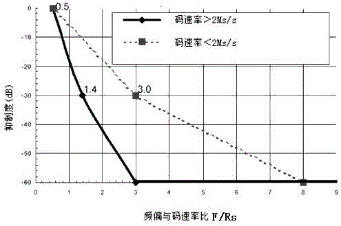
The former method uses an X-band cavity filter. According to the requirements, its bandwidth should be 2×R MHz, and the suppression at the center frequency ±R×1.4MHz must be greater than 30dB. Due to the narrow bandwidth, the rectangularity factor and quality factor are extremely demanding High, currently the cavity filter cannot meet the requirements in engineering
The latter method takes advantage of the high square coefficient of the SAW filter to filter the output spectrum of the digital transmission modulation at the intermediate frequency to achieve the required out-of-band suppression and mix the modulation signal to the X frequency band. This method avoids the X frequency cavity The design bottleneck of the body filter, although it can realize the out-of-band suppression of digital transmission, but it uses a lot of components, so it needs to use the cavity filter to suppress the local oscillator and image frequency in the X frequency band, and also needs to perform gain compensation, which has complex circuit and volume Disadvantages of large size, high power consumption and heavy debugging workload

Method used


Image

  • A space-borne x-band digital transmission out-of-band suppression device and method thereof
  • A space-borne x-band digital transmission out-of-band suppression device and method thereof
  • A space-borne x-band digital transmission out-of-band suppression device and method thereof

Examples


Embodiment Construction

[0034] The present invention will be further described below with reference to the accompanying drawings and specific embodiments.

[0035] The present invention will hereinafter be described in more detail with reference to the accompanying drawings, which illustrate embodiments of the invention. However, the present invention may be embodied in many different forms and should not be construed as limited by the embodiments set forth herein. Rather, these embodiments are presented so that this disclosure will be thorough and complete, and will fully convey the scope of the invention to those skilled in the art.

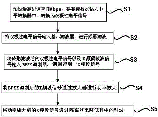
[0036] attached figure 2 A block diagram of a satellite-borne X-band digital transmission out-of-band suppression device provided by the present invention, as a preferred embodiment of the satellite-borne X-band digital transmission out-of-band suppression device provided by the present invention, the device at least includes : level shifter 1, baseband filter 2, B...


PUM


Abstract

The invention relates to a satellite-borne X-frequency band data transmission out-of-band rejection device and a satellite-borne X-frequency band data transmission out-of-band rejection method. The satellite-borne X-frequency band data transmission out-of-band rejection device comprises a level converter, a base band filter, a BPSK (Binary Phase Shift Keying) modulator, an X-frequency band carrier signal generator, an amplifier and an isolator. By converting the level of inputted low-frequency base band data, the satellite-borne X-frequency band data transmission out-of-band rejection device outputs a bipolar level signal, the data and an X-frequency band carrier signal are sent into the BPSK modulator to be modulated together after base band shaping filtration is performed by the base band filter, and therefore the data are modulated into the X frequency band. The output frequency spectrum of the BPSK modulator can meet the out-of-band rejection requirement, and the modulated data sequentially pass through the amplifier and the isolator and are then outputted to a solid-state amplifier or an antenna. The satellite-borne X-frequency band data transmission out-of-band rejection device can meet the out-of-band rejection requirement without affecting data transmission modulation characteristics and the data transmission communication error rate and with the same size, power consumption and weight, and is particularly applicable to projects with high working frequency and low data transmission bit rates, such as lunar exploration projects.

Description

technical field [0001] The invention relates to an out-of-band suppression technology for satellite-borne digital transmission, in particular to an out-of-band suppression device for satellite-borne X-band data transmission and a method thereof. Background technique [0002] In order to better promote international cooperation and avoid spectrum interference, the Advisory Committee on Space Data (CCSDS) has divided frequency bands for satellite measurement and control. It is becoming more and more serious, so there are corresponding requirements for the satellite downlink spectrum width. According to the 21-2R2 (SFCG21-2R2) template recommended by the Space Spectrum Coordination Group, such as figure 1 As shown, and the requirements of the measurement and control data transmission sub-system, the allowable spectrum frame of the effective spectrum of the space science service air-ground link, in the long-distance detection, due to the long communication distance, the data tr...

Claims


Application Information

Patent Timeline
Patent Type & Authority Patents(China)
IPC IPC(8): H04L25/03
Inventor 王文伟侯建文张玉花苗瑞琴
Owner SHANGHAI SPACEFLIGHT INST OF TT&C & TELECOMM
Learn More