Device and method for high-efficiency energy-saving combustion of low-heat value coal

A high-efficiency energy-saving, combustion method technology, applied in the direction of combustion methods, combustion equipment, gaseous fuel and powder fuel combustion, etc., can solve the problems of insufficient combustion emissions, low volatile component content, low calorific value, etc., and achieve emission The effect of reduction, high energy efficiency and low flame temperature

Inactive Publication Date: 2013-11-27
SHAANXI SHENGHUIYUAN INFORMATION SCI & TECH
View PDF5 Cites 5 Cited by
  • Summary
  • Abstract
  • Description
  • Claims
  • Application Information

AI Technical Summary

Problems solved by technology

These coal fuels with low calorific value and low volatile content do not meet the national environm

Method used


Image

  • Device and method for high-efficiency energy-saving combustion of low-heat value coal
  • Device and method for high-efficiency energy-saving combustion of low-heat value coal

Examples


Example Embodiment

[0022] Example one

[0023] In this embodiment, pulverized coal with a calorific value of 2500 calories is selected. The following experiments were conducted.

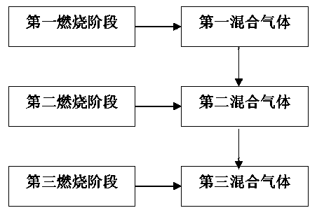
[0024] In the first stage of combustion, the atomized pulverized coal (fineness of 90 mesh) is first sent to the pulverized coal burner through the first blower, and the first blower blows in the mixed gas with a volume content of 60% (air gas volume). A mixed gas of 50% by volume and 50% by volume of water gas) and a mixed gas of 40% air at 250°C. The mixed gas is burned in the combustion chamber. The temperature of the combustion flame measured by the sensor is approximately 900°C. As the combustion process continues, under the continuous blowing action of the first blower, the combustion products of the first stage enter the solid combustion stage. In the solid combustion stage, the second blower blows in the mixed gas (air gas) with a volume content of 20%. A mixture of 50% by volume and 50% by volume of water gas), ...

Example Embodiment

[0031] Example three

[0032] In this embodiment, pulverized coal with a calorific value of 3000 calories is selected. The following experiments were conducted.

[0033] In the first stage of combustion, the atomized pulverized coal (fineness of 100 mesh) is sent to the pulverized coal burner through the first blower, and the first blower blows in the mixed gas with a volume content of 70% (air gas volume). The mixed gas is a mixture of 60% and 40% by volume of water gas) and 30% of air, and the mixed gas is burned in the combustion chamber. The temperature of the combustion flame measured by the sensor is about 920°C. As the combustion process continues, under the continuous blowing action of the first blower, the combustion products of the first stage enter the solid combustion stage. In the solid combustion stage, the second blower blows in a mixed gas (air gas) with a volume content of 15%. The volume ratio is 60%, water gas volume ratio is 40% mixed gas), 10% water vapor an...


PUM

PropertyMeasurementUnit
Finenessaaaaaaaaaa
Finenessaaaaaaaaaa

Abstract

The invention discloses a method for high-efficiency energy-saving combustion of low-heat value coal. The method comprises 1, a first combustion process: feeding pulverized coal of more than 80 meshes and first mixed gas into a pulverized coal combustor by an air blower, wherein the first mixed gas comprises, by volume, 60-70% of mixed gas and 30-40% of air, the mixed gas comprises, by volume, 50-75% of air gas and 25-50% of water gas and a mixed gas temperature is in a range of 250-280 DEG C, 2, a second combustion process: blowing second mixed gas into the pulverized coal combustor by a second air blower, wherein the second mixed gas comprises 10-20% of the mixed gas, 10% of vapor and 70-80% of air, and the second mixed gas comprises, by volume, 50-75% of air gas and 25-30% of water gas, and 3, a third combustion process: blowing third mixed gas into the pulverized coal combustor by a third air blower, wherein the third mixed gas comprises 10% of vapor and 90% of air and a temperature of the third mixed gas is in a range of 800-900 DEG C.

Description

technical field [0001] The invention relates to a coal combustion device and method, in particular to a high-efficiency and energy-saving combustion device and method for low calorific value coal. Background technique [0002] The efficiency of existing pulverized coal burners is low, and the highest combustion efficiency can only reach about 70%. With the burner being used for a long time, the combustion conditions deteriorate, and the combustion efficiency will be further reduced. [0003] At the same time, most burners use cheap coal with low calorific value as fuel for production, such as stone coal, oil shale, anthracite and other low-quality coal. The content of ingredients is low, but it is widely used in actual industry due to its low price. These coal fuels with low calorific value and low volatile content do not meet the national environmental protection requirements in terms of combustion emissions and seriously pollute the environment. In order to improve the...

Claims


Application Information

Patent Timeline
IPC IPC(8): F23C1/12F23L7/00
Inventor 贾晓玲曲维龙
Owner SHAANXI SHENGHUIYUAN INFORMATION SCI & TECH
Why Eureka
Try Eureka