Method and device for pulse-type quantitative fuel injection

A fuel injection device and pulse-type technology, which is applied in the direction of combustion method, liquid fuel supply/distribution, fuel supply adjustment, etc., can solve the problem of inability to switch fuel injectors in time and accurately, quantitative fuel injection, and fuel combustion. Waste combustion efficiency and other issues, achieve the effect of precise control of fuel injection volume, continuous operation and reliability, and improve fuel utilization

Inactive Publication Date: 2015-09-02
JIANGSU UNIV
View PDF1 Cites 0 Cited by
  • Summary
  • Abstract
  • Description
  • Claims
  • Application Information

AI Technical Summary

Problems solved by technology

At present, the fuel injection devices are continuous fuel injection, which cannot realize quantitative fuel injection, resulting in waste of combustion oil and low combustion efficiency
[0003] The Chinese patent application number is 99229291.3, and the name is a fuel oil heating furnace disclosed in the patent literature of a kind of automatic control furnace temperature. The fuel injection nozzle device is fixed on the furnace wall. The oil tank is connected, and a solenoid valve is set on the oil pipeline connected with the fuel injector device. The solenoid valve is connected with the thermal sensor installed in the furnace cavity through a set of automatic temperature control system. Through the thermal sensor, automatic temperature control system, Solenoid valves and fuel injectors are used to control the work of the fuel injectors. However, the fuel injector device on the fuel heating furnace has the following disadvantages: First, the fuel injector device has a large fuel injection inertia and cannot switch the fuel injection in a timely and accurate manner. Nozzle, which affects the accuracy of fuel injection; second, the fuel injector device is a continuous fuel injection, which cannot be quantitatively injected, and the injected fuel cannot be completely combusted, which affects the fuel combustion efficiency

Method used


Image

  • Method and device for pulse-type quantitative fuel injection
  • Method and device for pulse-type quantitative fuel injection
  • Method and device for pulse-type quantitative fuel injection

Examples


Embodiment Construction

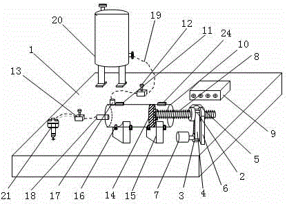
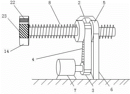
[0017] see figure 1 and figure 2 , the bottom of the present invention is a rigid base 1, on which a constant pressure oil storage tank 20 is fixedly installed, and the base 1 and the constant pressure oil storage tank 20 both form an integration. The constant pressure oil storage tank 20 connects the piston type to the several warehouses 10 through the oil delivery pipe 19, and supplies oil to the piston type to the several warehouses 10. The first electromagnetic valve 12 is installed on the oil delivery pipe 19 between the constant pressure oil storage tank 20 and the piston feeder warehouse 10 . The piston-type feeding chamber 10 is provided with an oil inlet port 17 and an oil outlet port 18 , and the constant pressure oil storage tank 20 is connected to the oil inlet port 17 through an oil delivery pipe 19 . The oil outlet port 18 is mechanically connected to the nozzle 21 through another oil delivery pipe 19, and the nozzle 21 adopts a mechanical large-flow nozzle, w...


PUM


Abstract

The invention discloses an impulse-type quantified oil injection method and device. A constant-pressure oil storage tank is connected with a piston feeding bin through one oil conveying pipe. A first electromagnetic valve is arranged on the one oil conveying pipe. The piston-type feeding bin is connected with a nozzle through the other oil conveying pipe. A second electromagnetic valve is arranged on the other oil conveying pipe. A piston which makes contact with the inner wall of the piston-type feeding bin in a sealed mode is arranged in an inner cavity of the piston-type feeding bin. The piston is connected with the left end of a lead screw through a rolling bearing. The right end of the lead screw stretches out of the piston-type feeding bin and is in sleeved connection with a toothed nut. The toothed nut is connected with a gear through a toothed belt. The gear is connected with an output shaft of a stepping motor. A left sensor and a right sensor which detect the left limiting position and the right limiting position of the piston are arranged on the piston-type feeding bin. The left sensor, the right sensor, the first electromagnetic valve, the second electromagnetic valve and the stepping motor are respectively connected with an embedded controller. The stepping motor drives the piston to have the accurate displacement amount inside the feeding bin, the quantified oil injection can be selectively carried out according to the actual combustion condition inside a furnace, oil combustion waste can be reduced, and the combustion efficiency inside the furnace is improved.

Description

technical field [0001] The invention relates to an oil injection device, which is an essential key component in the structure of an industrial boiler, in particular, an oil injection device capable of precisely controlling the amount of oil injection for the boiler. Background technique [0002] Industrial boilers are one of the important thermal power equipments. Industrial boilers are still in a production state with high energy consumption, large waste and serious environmental pollution. The reasonable and appropriate amount of fuel injection of the fuel injection device in the industrial boiler plays a vital role in the full combustion of the combustibles in the industrial boiler. The current fuel injection devices are continuous fuel injection, which cannot realize quantitative fuel injection, resulting in waste of combustion oil and low combustion efficiency. [0003] The Chinese patent application number is 99229291.3, and the name is a fuel oil heating furnace disc...

Claims


Application Information

Patent Timeline
Patent Type & Authority Patents(China)
IPC IPC(8): F23K5/02F23N1/00
Inventor 张荣标邱亮钱避违
Owner JIANGSU UNIV
Why Eureka
Try Eureka