Multi-axis system error modeling and measuring device and method based on optical free-form surface

A system error and measurement method technology, applied in the direction of measuring devices, optical devices, instruments, etc., can solve the problems of low measurement accuracy, limit large-scale promotion and application, increase the time for measuring geometric errors of machine tools, and reduce the cost of measurement , high-precision measurement, and easy operation

Inactive Publication Date: 2013-11-27
TIANJIN UNIV
View PDF5 Cites 22 Cited by
  • Summary
  • Abstract
  • Description
  • Claims
  • Application Information

AI Technical Summary

Problems solved by technology

Although the traditional measurement method has low measurement cost, the installation and debugging of the measurement device is complicated, which increases the time for measuring the geometric error of the machine tool, affects the normal production and processing of the machine tool, and has low measurement accuracy, let alone realize the comprehensive measurement of the geometric error of the machine tool
The new dual-frequency laser interferometer is used to measure the geometric error of the machine tool. Although the measurement accuracy is high, various geometric errors of the machine tool can also be obtained through the corresponding modeling method, but the cost of the laser interferometer and its supporting devices is high, which limits its large-scale Promoted application of

Method used


Image

  • Multi-axis system error modeling and measuring device and method based on optical free-form surface
  • Multi-axis system error modeling and measuring device and method based on optical free-form surface
  • Multi-axis system error modeling and measuring device and method based on optical free-form surface

Examples


Embodiment Construction

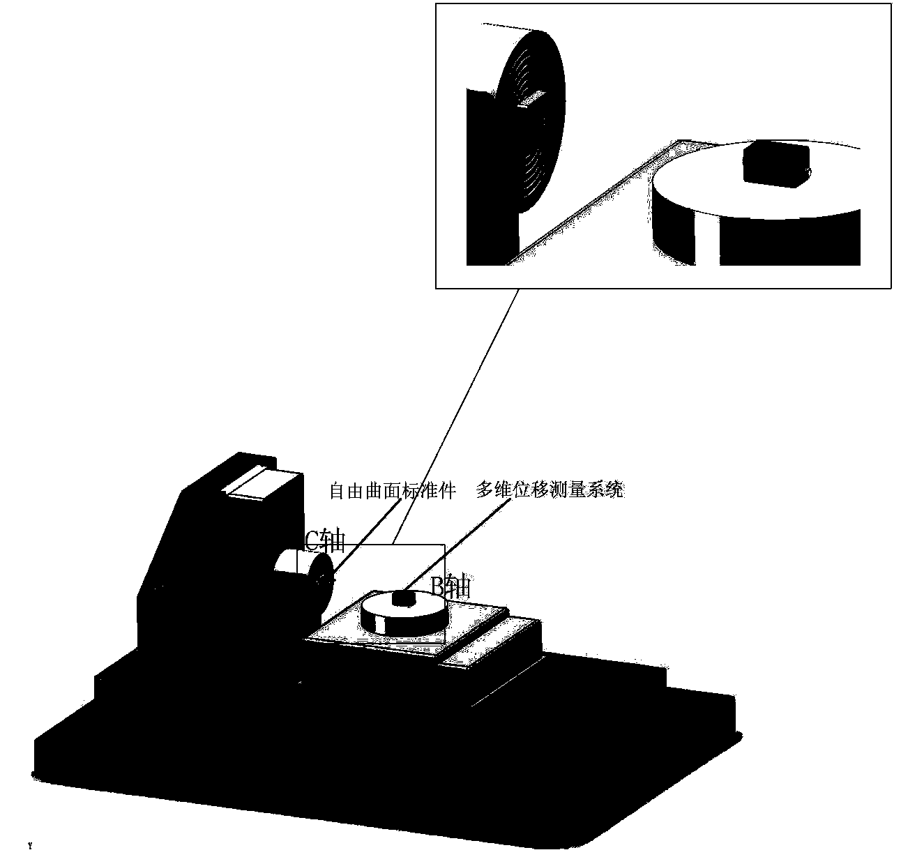
[0032] Taking the multi-axis numerical control machine tool as an example, the present invention adopts an optical free-form surface as the strategy of measuring the standard part, and realizes the high-precision and low-cost measurement of the geometric error of the numerical control machine tool. The present invention will be described in further detail below according to the accompanying drawings and examples.

[0033] (1) Machine tool error modeling

[0034] The invention adopts the method based on the multi-body system theory to realize the establishment of the mathematical model of the geometric error of the machine tool. The five-axis CNC machine tool contains 5 relative moving bodies, and each moving body m will generate 6 errors T during the movement process mx , T my , T mz , R mx , R my and R mz . Among them, T represents the movement error, and R represents the rotation error. The first subscript m represents the name of the moving body, and m can be X guid...


PUM


Abstract

The invention belongs to the field of multi-axis system detection, and provides a novel measuring method high in precision, low in cost and capable of comprehensively measuring multi-axis system geometrical errors. An optical free-form surface serves as a multi-axis system error measuring standard component, a multi-axis system error measuring path is planned through a corresponding error modeling method, a multi-dimensional displacement measuring system is utilized to detect the optical free-form surface, comprehensive measuring for the multi-axis system geometrical errors is achieved, and then the multi-dimensional displacement measuring system is used for compensating the multi-axis system geometrical errors. To realize the purpose, the technical scheme provides a multi-axis system error modeling and measuring device and method based on an optical free-form surface. The multi-axis system error modeling and measuring device comprises a semiconductor laser, a collimation beam-shrinking system, a four-quadrant photodiode QPD, an imaging lens, a 1 / 4 wave plate, an optical free-form surface standard component, a polarization splitting prism PBS, an image detector CCD, another imaging lens and a data acquisition and processing platform. The multi-axis system error modeling and measuring device and method are mainly used for multi-axis system detection.

Description

technical field [0001] The invention belongs to the field of multi-axis system detection, and specifically relates to a multi-axis system error modeling and measuring device and method based on an optical free-form surface. technical background [0002] With the rapid development of modern science and technology, multi-axis systems such as multi-axis CNC machine tools, three-coordinate measuring machines, multi-axis translation stages, and multi-axis manipulators have been widely used in many fields such as industrial production and industrial inspection. With the continuous development of modern industry towards high precision and diversification, it is of great significance to improve the precision of multi-axis systems. A multi-axis CNC machine tool is a typical representative of a multi-axis system. The background technology of the present invention will be described below by taking a multi-axis CNC machine tool as an example. [0003] As the foundation and core of manu...

Claims


Application Information

Patent Timeline
IPC IPC(8): G01B11/03
Inventor 房丰洲朱朋哲万宇
Owner TIANJIN UNIV
Why Eureka
Try Eureka