Scanning radar super-resolution imaging method

A super-resolution imaging and scanning radar technology, applied in the field of radar, can solve the problems of a large number of samples, unsuitable for real-time imaging of scanning radar, and the limitation of the real aperture length of the resolution.

Active Publication Date: 2013-11-27
UNIV OF ELECTRONICS SCI & TECH OF CHINA
View PDF2 Cites 29 Cited by
  • Summary
  • Abstract
  • Description
  • Claims
  • Application Information

AI Technical Summary

Problems solved by technology

Scanning radar imaging is an important imaging method for radar stationary platforms and moving platforms. In scanning radar imaging, high resolution can be obtained by matching the chirp signal in the range direction, but the resolution in the azimuth direction is limited by the real aperture. length limit
[0003] For scanning radar imaging, especially how to improve the azimuth resolution, the document "A new Sector Imaging Radar for Enhanced Vision–SIREV, SPIE Conference on Enhanced and Synthetic Vision, 1999, pp.39-47, Florida", uses the array The antenna forms an aperture to increase the real aperture of the antenna, but the size of the platform limits the expansion of the antenna aperture, resulting in a limited improvement in azimuth resolution; the literature "Iterative Noncoherent Angular Superresolution, IEEE National Radar Conference, pp.100–105.1988" , and "Radar angular superresolution algorithm based on Bayesian approach, IEEE Int.Conf.on Signal Processing, Dallas, TX, USA, March, 2010, pp.1894-1897", the azimuth echo is modeled as an antenna pattern Convolution with the scene target, and use the deconvolution method to improve the azimuth resolution, but this kind of method is not robust when the signal-to-noise ratio is low, and it is prone to false targets; the literature "Superresolution for Scanning Antenna, Radar Conference , 1997, IEEE National, pp:306-308" proposed a SMUSIC algorithm, this method uses the second-order statistical properties of the scanning echo to super-resolution the target, but this method requires a large number of samples and is not suitable for scanning radar live imaging

Method used


Image

  • Scanning radar super-resolution imaging method
  • Scanning radar super-resolution imaging method
  • Scanning radar super-resolution imaging method

Examples


Embodiment Construction

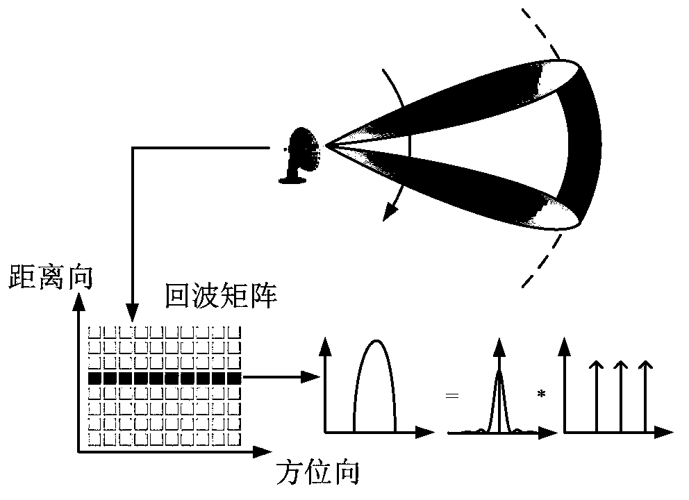
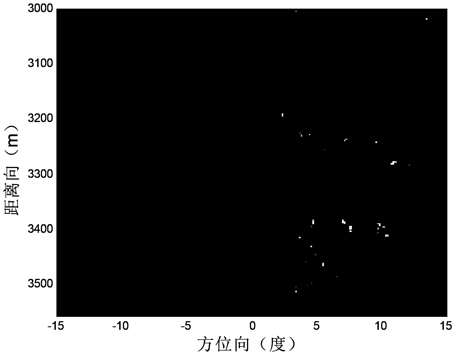
[0036] figure 1 It is a schematic diagram of scanning radar imaging in this embodiment, and the original imaging scene is as follows figure 2 shown. where the antenna azimuth beamwidth is θ w =3°, the scanning range of the antenna is ±15°, the scanning speed is ω=60° / s, the wavelength of the transmitted signal is λ=0.03m, the bandwidth is B=50MHz, and the frequency modulation slope is K r =2.5×10 13 Hz / s chirp signal. Pulse repetition frequency PRF=1000, azimuth sampling points K=500. Figure 5 It is the original echo obtained after the radar scans the scene.

[0037] In the following discussion, only a certain distance R is considered 0 Target upwards in all directions. Assuming that in the scanning area, there are targets at each azimuth sampling point, let the position parameters of these targets be θ=(θ 1 ,θ 2 ,…,θ K ), the magnitude parameter is σ=(σ 1 ,σ 2 ,…,σ K ), then these target echo signals after coherent demodulation can be expressed as:

[0038] ...


PUM


Abstract

The invention discloses a scanning radar super-resolution imaging method. The method comprises the following steps of: performing distance-to-pulse compression; constructing a convolution matrix; initializing the convolution matrix; calculating an echo autocorrelation matrix; regularizing the echo autocorrelation matrix; performing orientation-to-parameter estimation; judging whether iteration is performed until a convergence state appears; and outputting super-resolution imaging results. According to the scanning radar super-resolution imaging method, an orientation-to-echo spectrum estimation model is constructed according to a radar antenna scanning process; a scanning radar imaging problem is converted into a parameter estimation problem; and amplitude and orientation estimation is performed on a site through an iteration self-adaptive method. Compared with an existing method, the scanning radar super-resolution imaging method can be applicable to low signal-to-noise ratio and has high robustness; and at the same time, with the scanning radar super-resolution imaging method adopted, robust imaging results can be obtained with a single times of scanning.

Description

technical field [0001] The invention belongs to the technical field of radar, relates to radar imaging, and in particular relates to a scanning radar azimuth super-resolution method. Background technique [0002] With its advantages of strong penetration, all-weather, large dynamic range and high imaging quality, radar imaging technology has become an irreplaceable technical means in the field of detection today, and is playing an increasingly important role in many fields. Scanning radar imaging is an important imaging method for radar stationary platforms and moving platforms. In scanning radar imaging, high resolution can be obtained by matching the chirp signal in the range direction, but the resolution in the azimuth direction is limited by the real aperture. Length restrictions. [0003] For scanning radar imaging, especially how to improve the azimuth resolution, the document "A new Sector Imaging Radar for Enhanced Vision–SIREV, SPIE Conference on Enhanced and Synth...

Claims


Application Information

Patent Timeline
Patent Type & Authority Applications(China)
IPC IPC(8): G01S13/89
Inventor 张永超李文超张桂梅黄钰林杨建宇张寅蒋文
Owner UNIV OF ELECTRONICS SCI & TECH OF CHINA
Why Eureka
Try Eureka