Zero-current soft switching converter

A soft-switching and converter technology, applied in the direction of adjusting electrical variables, converting DC power input to DC power output, high-efficiency power electronic conversion, etc. , to achieve the effect of strengthening the effect

Active Publication Date: 2013-11-27
BEIJING JIAOTONG UNIV
View PDF2 Cites 17 Cited by
  • Summary
  • Abstract
  • Description
  • Claims
  • Application Information

AI Technical Summary

Problems solved by technology

[0006] Aiming at the deficiencies of the prior art, the present invention provides a zero-current soft-switching converter, which overcomes the problem that the resonant current does not change monotonously with the load current when the soft-switching of the existing ZCS and ZVS converters works, and solves the problem that the resonant current amplitude automatically follows The problem of load current change

Method used


Image

  • Zero-current soft switching converter
  • Zero-current soft switching converter
  • Zero-current soft switching converter

Examples


Embodiment 1

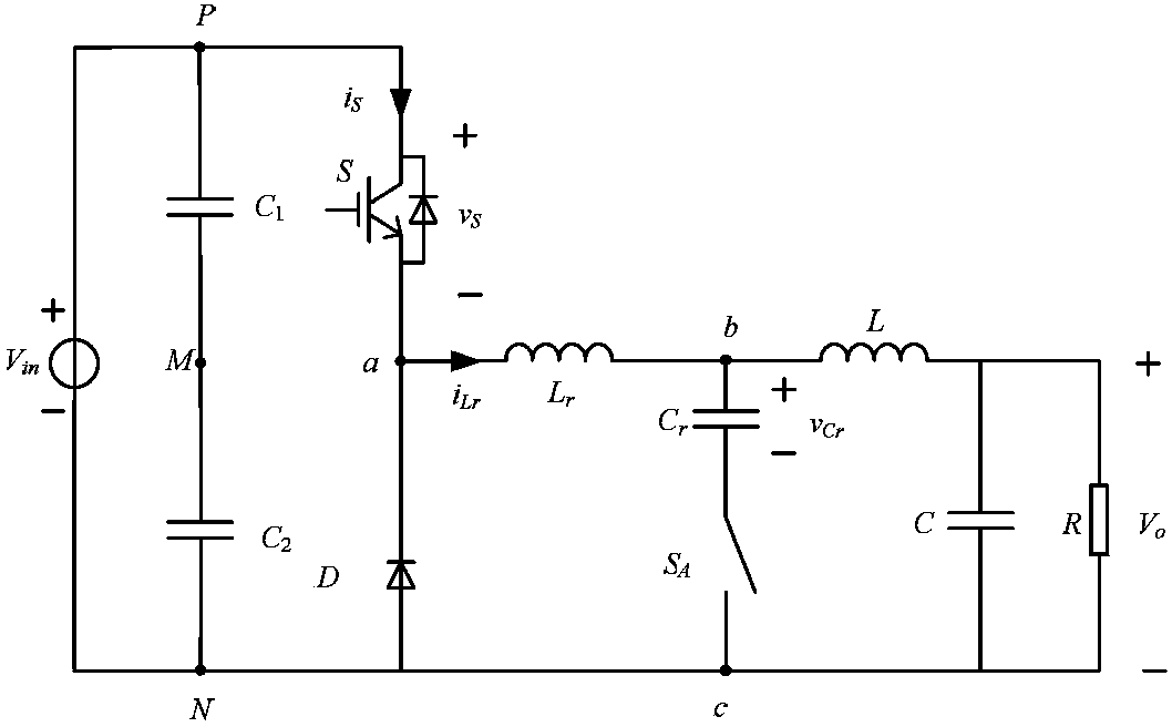
[0052] As shown in Figure 1(a), the embodiment of the present invention provides a zero-current soft-switching converter, which includes a basic circuit including a switching tube, a power diode, a current source inductor, and an input voltage source, and also includes a soft-switching auxiliary unit,

[0053] As shown in Figure 3(a), the soft switching auxiliary unit includes a resonant inductor L r , Resonant capacitance C r and auxiliary switch S A ;

[0054] Wherein, the switch tube and the auxiliary switch tube S A IGFBTs or MOSFETs carrying anti-parallel diodes and other power switching devices with anti-parallel diode functions that can be turned off;

[0055] The resonant inductance L r One end a of the switch tube is connected to the connection point of the switch tube and the power diode, or connected to the midpoint of the bridge arm formed by connecting two switch tubes in series; the resonant inductance L r The other end b of is connected to the current sourc...

Embodiment 2

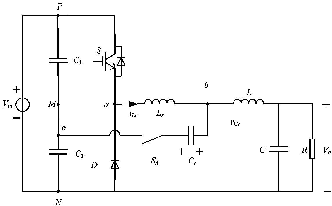
[0128] As shown in Figure 1(a)~(c), the basic circuit is a Buck converter, including a current source inductor L, an input voltage source V in , the resonant inductance L r One end a of the switch tube S is connected to the connection point of the power diode D, and the resonant inductor L r The other terminal point b of is connected to the current source inductance; the resonant capacitor C r One end with the resonant inductor L r terminal b is connected, the resonant capacitor C r with the auxiliary switch S A connected to form a series branch, the auxiliary switch S A The other end c is connected to the voltage source V in On the negative pole point N, or on the positive pole point P, or on the voltage divider point M between the positive and negative pole points.

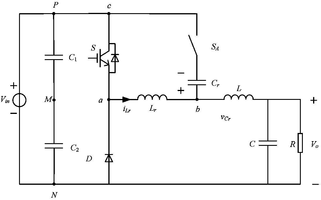
[0129] As shown in Figure 1 (d) to (f), as a modification of this embodiment, the auxiliary switch tube S in the soft switch auxiliary unit A and resonant capacitor swapped positions: the auxiliary switch...

Embodiment 3

[0131] As shown in 4(a), the basic circuit is a Boost converter, including a current source inductor L and an output voltage source V o ,

[0132] The resonant inductance L r One end a of the switch tube S is connected to the connection point of the power diode D, and the resonant inductor L r The other end point b of is connected to the current source inductance L; the resonant capacitor C r with the auxiliary switch S A form a series branch, one end of the series branch and the resonant inductance L r Terminal b is connected, and the other terminal c of the series branch is connected to the voltage source V o On the negative pole point N, or on the positive pole point P, or on the voltage divider point M between the positive and negative pole points.

[0133] Figure 4(a) is a topological structure diagram of this embodiment; as in embodiment 2, when the basic circuit is a Boost converter, there are also various deformed topological structures by changing the connection ...


PUM


Abstract

The invention provides a zero-current soft switching converter and relates to the field of power electronic circuit topology design. The zero-current soft switching converter comprises a switching tube, a power diode, a voltage source inductor basic circuit and a current source inductor basic circuit, and further comprises a soft switching auxiliary unit. The soft switching auxiliary unit comprises a resonance inductor, a resonance capacitor and an auxiliary switching tube. The switching tube and the auxiliary switching tube are turn-off power switching devices provided with antiparallel diodes or having antiparallel diode characteristics. One end a of the resonance inductor is connected to a connection point of the switching tube and the power diode, and the other end b of the resonance inductor is connected to a current source inductor. The resonance capacitor and the auxiliary switching tube form a serial branch, one end of the serial branch is connected with an end b of the resonance inductor, and the other end c of the serial branch is connected to the negative pole N or the positive pole P or the middle point M of a voltage source. According to the zero-current soft switching converter, resonance current amplitude values of the soft switching converter can be automatically changed along with load current, therefore, loss of the soft switching converter can be further lowered, and efficiency can be further improved.

Description

technical field [0001] The invention relates to the field of power electronic circuit topology design, in particular to a zero-current soft-switching converter. Background technique [0002] Zero-current switching (ZCS) refers to turning off the device when the current flowing through the switching device is zero, and turning on the device when the current of the series inductance of the device is zero; zero-voltage switching (ZVS) refers to turning on the device when the withstand voltage of the switching device is zero. The device is turned off when the voltage of the device and the parallel capacitance of the device is zero; [0003] At present, when the existing ZCS converter and ZVS converter work in soft switching, the resonant capacitor voltage does not change with the load current, so the resonant current amplitude of soft switching hardly changes with the change of the load current. [0004] This makes the existing ZCS and ZVS soft-switching converters work at ligh...

Claims


Application Information

Patent Timeline
Patent Type & Authority Applications(China)
IPC IPC(8): H02M3/155H02M1/08
CPCY02B70/1491Y02B70/10Y02P80/10
Inventor 郑琼林邵天骢韩娜李艳张立伟游小杰刘建强李虹孙湖
Owner BEIJING JIAOTONG UNIV
Why Eureka
Try Eureka