Device and method for measuring dynamic extinction ratio of pulsed light with high dynamic range

A high dynamic range, measurement device technology, applied in the field of optical fiber communication and optical fiber sensing, to achieve the effect of broad application fields, suppression of operating point drift, and intuitive measurement results

Active Publication Date: 2013-11-27
NANJING UNIV
View PDF3 Cites 11 Cited by
  • Summary
  • Abstract
  • Description
  • Claims
  • Application Information

AI Technical Summary

Problems solved by technology

[0004] The technical problem to be solved by the present invention is to eliminate the shortcomings of the traditional pulsed light dynamic extinction ratio measurement method, and provide a pulsed light dynamic extinction ratio measurement device with a high dynamic range. The signal is coherently measured, and the relative power of the peak value of the pulsed light to be measured, the background and the dark current noise of the photodetector can be obtained at one time for the calculation of the dynamic extinction ratio. It not only has high measurement efficiency and a large dynamic range, but also effectively suppresses the Measure the effect of device operating point drift, which can eliminate the limitations of traditional measurement methods

Method used


Image

  • Device and method for measuring dynamic extinction ratio of pulsed light with high dynamic range
  • Device and method for measuring dynamic extinction ratio of pulsed light with high dynamic range
  • Device and method for measuring dynamic extinction ratio of pulsed light with high dynamic range

Examples


Embodiment Construction

[0026] The technical solution of the present invention will be further described in detail below in conjunction with the accompanying drawings.

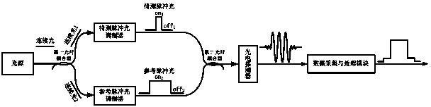
[0027] Such as figure 1 As shown, the present invention provides a pulsed light dynamic extinction ratio measuring device with a high dynamic range, including a light source, a first fiber coupler, a pulse light modulator to be tested, a reference pulse light modulator, a second fiber coupler, A photodetector, a data acquisition and processing module, the light source outputs continuous light to the first fiber coupler, and the first fiber coupler divides the continuous light into two beams of continuous light and inputs them to the pulse light modulator to be measured and the reference pulse respectively Optical modulator; the pulsed light modulator to be tested modulates continuous light into pulsed light to be measured and outputs it to the second fiber coupler; the reference pulsed light modulator modulates continuous light into ...


PUM


Abstract

The invention discloses a device and method for measuring the dynamic extinction ratio of pulsed light with a high dynamic range. The device comprises a light source, a first optical fiber coupler, a modulator of pulsed light to be measured, a modulator of reference pulsed light, a second optical fiber coupler, a photoelectric detector and a data collecting and processing module. Two beams of continuous light divided from continuous light are modulated into the pulsed light to be measured and the reference pulsed light, beat frequency optical signals produced after the pulsed light to be measured and the reference pulsed light are in coherent coupling are converted into beat frequency current signals, the beat frequency current signals are processed, electric power of pulse peak optical power and electric power of substrate optical power of the pulsed light to be measured, and electric power of PD dark current noise are obtained, and the dynamic extinction ratio of the pulsed light to be measured is calculated according to the obtained electric power. Through single measurement, the power of the peak and the power of the substrate of the pulsed light to be measured and the power of the dark current noise of the photoelectric detector are obtained at the same time, the dynamic extinction ratio of the pulsed light is measured, the measurement efficiency is high, the precision is high, and the dynamic range is large.

Description

technical field [0001] The invention relates to a pulsed light dynamic extinction ratio measurement device and method, in particular to a measurement of the pulsed light dynamic extinction ratio with a large dynamic range for communication or sensing, and belongs to the fields of optical fiber communication and optical fiber sensing. Background technique [0002] In recent years, optical fiber communication technology and optical fiber sensing technology have developed rapidly and received more and more attention. Pulsed light is indispensable in fiber optic communication systems and fiber optic sensing systems, and the dynamic extinction ratio of pulsed light is an important parameter to measure the signal-to-noise ratio of fiber optic communication systems and fiber optic sensing systems. Therefore, knowing the dynamic extinction ratio of pulsed light is beneficial to the estimation of the signal-to-noise ratio of the optical fiber communication system and the optical fibe...

Claims


Application Information

Patent Timeline
Patent Type & Authority Applications(China)
IPC IPC(8): H04B10/075
Inventor 张旭苹张益昕武学林唐志强应宙锋
Owner NANJING UNIV
Why Eureka
Try Eureka