Oily sewage filter and filtering method

A sewage filter and filter material technology, which is applied to chemical instruments and methods, fixed filter element filters, filter circuits, etc., can solve the problems of filter material replacement, reduced treatment effect, and high operating costs, so as to reduce backwash water The effect of increasing the dosage, improving the regeneration effect, and reducing the operating cost

Active Publication Date: 2013-12-04
SHENZHEN BUSTIN TECH
View PDF5 Cites 5 Cited by
  • Summary
  • Abstract
  • Description
  • Claims
  • Application Information

AI Technical Summary

Problems solved by technology

[0002] The composition of industrial oily sewage is complex, and there are floating oil, sediment and oily solids. At present, the advanced treatment of large volumes of oily sewage mainly uses dual-media or multi-media filters and fiber ball filters for treatment. When using these equipment for treatment, the water All pollutants (oil slick, sediment, and solid matter) are all absorbed and screened through the filter material, and backwashed after the filter material is saturated. During backwashing, the pollutants are separated from the filter material under the action of stirring, and the specific gravity is relatively Light pollutants are discharged from the backwash outlet of the upper part of the filter under the action of water flow, and heavy pollutants cannot be taken away by water and remain in the filter material at the bottom of the filter. After a long period of time, the filter material begins to harden, and the slick oil is not easy to discharge in time , the treatment effect is reduced, and eventually the effluent does not meet the standard, and the filter material must be replaced; it is sensitive to sediment, and when the sewage has a high sediment content, it needs to be equipped with a pre-stage desander for pretreatment, and the instantaneous flow of backwash water is required to be large, and oil slicks are required. The investment cost of sediment pretreatment is relatively high, the filter material life is short and the backwash water requires a large flow rate, resulting in high operating costs. The filter material life of existing filters is generally about 6 months

Method used


Image

  • Oily sewage filter and filtering method

Examples


Embodiment Construction

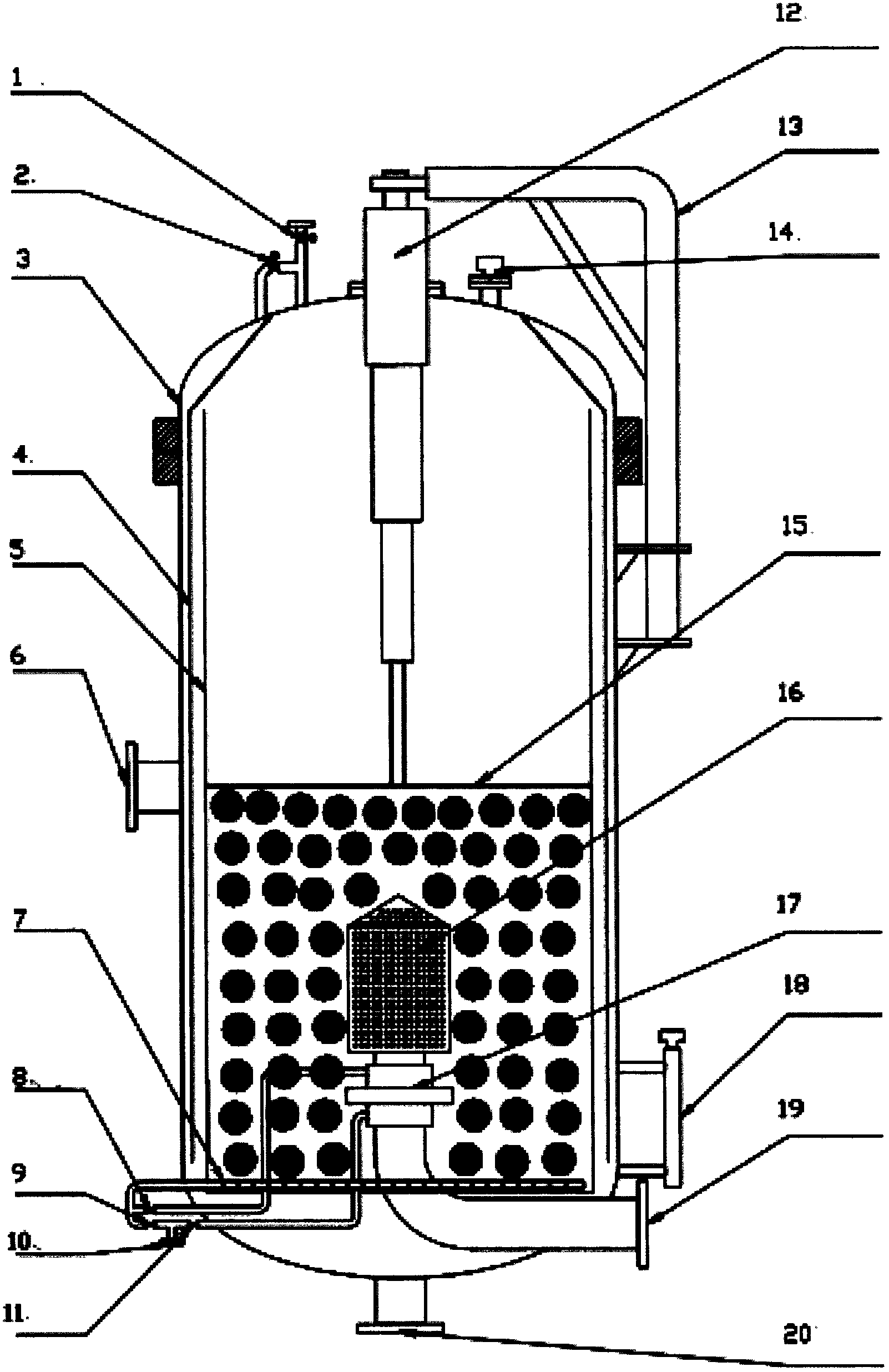
[0026] The oily sewage filter and the oily sewage filtering method of the present invention will be further described in detail below in conjunction with the accompanying drawings and specific embodiments.

[0027] As shown in the figure, the oily sewage filter of the present invention includes a tank body 3 and a water inlet 6 arranged in the middle of the tank body, an interface instrument 14 is arranged above the tank body 3, and a liquid level gauge 18 is arranged below the tank body; The inside of the tank body 3 is provided with a swirl partition 4 forming an annular swirl area with the side wall of the tank body. The inside of the swirl partition 4 is provided with a perforated net 5 forming a filter material filling area. The perforated pressure plate 15 that can divide the filter material filling area into upper and lower parts, the upper part of the filter material filling area and the upper part of the swirling flow area are oil slick accumulation areas, and the lowe...


PUM


Abstract

Disclosed are an oily wastewater filter for advanced treatment of large amounts of oily wastewater and a filtering method for the oily wastewater. The filter comprises a tank and a water inlet. Arranged within the tank is a swirl baffle. Arranged on the inside of the swirl baffle is a perforated mesh forming a filter media-filled area. Arranged within the perforated mesh is a perforated platen. The upper portion of the filter media-filled area and the upper portion of a swirl area are a slick accumulation area. The lower portion of the filter media-filled area is a sediment accumulation area. Arranged within the tank is a cylinder. Also arranged above the tank is a connection pipe connecting the swirl area and the filter media-filled area. Arranged at the bottom of the tank is a backwash discharge outlet. Employment of this structure provides the slick and sediment with definitive disposal sites, reduces pollution of filter media, reduces backwash water energy consumption and backwash water consumption, while the technical solution of suspended filter media, forced stirring, and entirely discharged backwash bottom allows for greatly improved regeneration effect of the filter media and prevents a compaction phenomenon, thus greatly extending the service life of the filter media and reducing operating costs.

Description

technical field [0001] The invention relates to an oily sewage filter for advanced treatment of oily sewage with a large amount of water and a filtering method for oily sewage, belonging to the technical field of sewage treatment. Background technique [0002] The composition of industrialized oily sewage is complex, including floating oil, sediment, and oily solids. Currently, the advanced treatment of large volumes of oily sewage mainly uses dual-media or multi-media filters and fiber ball filters. All pollutants (oil slicks, sediment, and solids) are all absorbed and screened through the filter material, and backwashed after the filter material is saturated. During backwashing, the pollutants are separated from the filter material under the action of stirring, and the specific gravity Light pollutants are discharged from the backwash outlet of the upper part of the filter under the action of water flow, and heavy pollutants cannot be taken away by water and remain in the ...

Claims


Application Information

Patent Timeline
Patent Type & Authority Applications(China)
IPC IPC(8): B01D36/04C02F1/40
CPCC02F2101/32C02F2303/16B01D29/66B01D17/10B01D29/114C02F1/40C02F1/004B01D36/04Y02A20/152
Inventor 陈妙瑜
Owner SHENZHEN BUSTIN TECH
Why Eureka
Try Eureka