Energy-saving control method of hydraulic system of hydraulic rolling shear

A hydraulic system, energy-saving control technology, applied to fluid pressure actuated system components, shearing devices, shearing equipment, etc., can solve problems such as pressure oil leakage, hydraulic system oil temperature rise, and electric energy waste, so as to improve the use of Efficiency, reducing power loss, and reducing temperature rise

Inactive Publication Date: 2013-12-04
TAIYUAN UNIVERSITY OF SCIENCE AND TECHNOLOGY +1
View PDF6 Cites 9 Cited by
  • Summary
  • Abstract
  • Description
  • Claims
  • Application Information

AI Technical Summary

Problems solved by technology

[0002] When the hydraulic rolling shear is working, the hydraulic system needs a large amount of oil supply only when the steel plate is cut. When the steel plate is not cut, the oil in the system flows back to the oil tank through the overflow valve. This part of the oil not only causes electric energy in the hydraulic system The waste of waste also increases the oil temperature of the hydraulic system of the rolling shears, and the pressure oil leaks, which affects the life and working accuracy of the rolling shears

Method used


Image

  • Energy-saving control method of hydraulic system of hydraulic rolling shear

Examples


Embodiment Construction

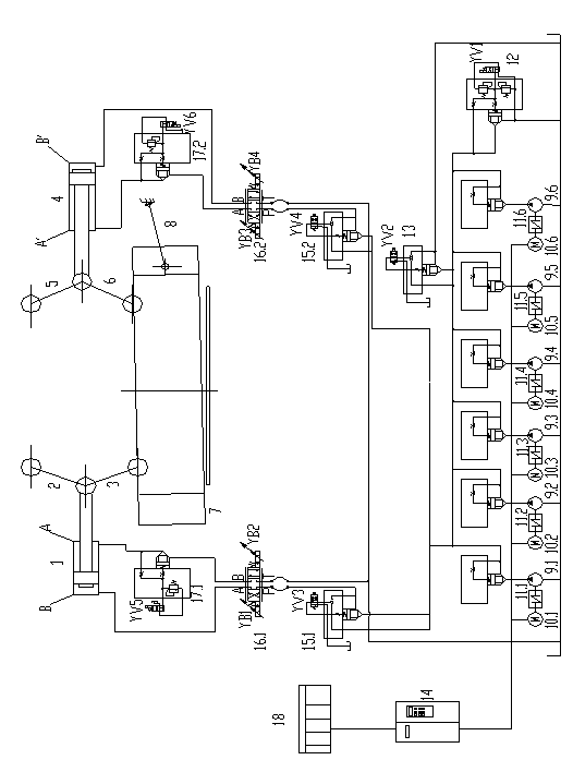
[0010] Such as figure 1 As shown, press the cutting start button, the rolling shears start to cut the steel plate, and the PLC programmable controller 18 controls the frequency converter 14 to make the frequency conversion motors 10.1, 10.2, 10.3, 10.4, 10.5, 10.6 drive the column according to the given speed The plug pumps 9.1, 9.2, 9.3, 9.4, 9.5, and 9.6 supply oil to the system. At the same time, the electromagnet YV1 of the plug-in relief valve 12 is energized, the hydraulic system is loaded, and the system pressure rises. The plug-in electromagnetic check valve 15.1 The electromagnet YV3 is energized, and the pressure oil enters the rodless chamber B of the hydraulic cylinder 1 through the pressure oil port P of the servo proportional valve 16.1, and pushes the piston rod to move to the right. When the piston rod of the hydraulic cylinder 1 reaches the required position , the electromagnet YV2 of the plug-in electromagnetic directional control valve 13 is energized, and t...


PUM


Abstract

An energy-saving control method of a hydraulic system of hydraulic rolling shear belongs to the technical field of hydraulic transmission control of the hydraulic rolling shear. The hydraulic system comprises variable-frequency motors, a frequency converter, a PLC (programmable logic controller), plunger pumps and hydraulic valves. The energy-saving control method of the hydraulic system of the hydraulic rolling shear is characterized in that action commands of two hydraulic cylinders of the hydraulic rolling shear are input into the frequency converter through the PLC, and the frequency converter changes the rotational speeds of the variable-frequency motors according to commands of the PLC to enable the plunger pump group to variably output hydraulic oil. The hydraulic system can adjust the oil supply amount of the plunger pumps according to requirements of steel plate shearing of the hydraulic rolling shear at any time, after the steel plate shearing is finished, the variable-frequency motors stop rotating according to commands, accordingly the plunger pumps stop supplying the oil to the system, and at the time the hydraulic system is in a non-energy-consumption state to reduce energy loss.

Description

technical field [0001] The invention belongs to the technical field of hydraulic transmission control of hydraulic rolling shears, and in particular relates to energy-saving control of a hydraulic system of hydraulic rolling shears. Background technique [0002] When the hydraulic rolling shear is working, the hydraulic system needs a large amount of oil supply only when the steel plate is cut. When the steel plate is not cut, the oil in the system flows back to the oil tank through the overflow valve. This part of the oil not only causes electric energy in the hydraulic system The waste of waste will also increase the oil temperature of the hydraulic system of the rolling shears, and the pressure oil will leak, which will affect the life and working accuracy of the rolling shears. [0003] At present, the invention patent with the patent number "2008100802257" filed by Taiyuan University of Science and Technology and Taiyuan University of Science and Technology Heavy ...

Claims


Application Information

Patent Timeline
Patent Type & Authority Applications(China)
IPC IPC(8): B23D15/14B23D15/08F15B21/02
CPCY02P70/10
Inventor 韩贺永朱琳李宏杰马立峰黄庆学
Owner TAIYUAN UNIVERSITY OF SCIENCE AND TECHNOLOGY
Why Eureka
Try Eureka