self-charging electric vehicle

An electric vehicle, self-charging technology, used in electric vehicles, electric traction, vehicle energy storage, etc.

Active Publication Date: 2016-05-04
朱建荣
View PDF6 Cites 0 Cited by
  • Summary
  • Abstract
  • Description
  • Claims
  • Application Information

AI Technical Summary

Problems solved by technology

In fact, before I invented this "one machine with two uses" function, I had already developed and tested a set of vehicle brake power generation equipment. It can only send out a charging current of 800mA, which is 1.5 times smaller than this power generation effect.

Method used


Image

  • self-charging electric vehicle
  • self-charging electric vehicle

Examples


Embodiment Construction

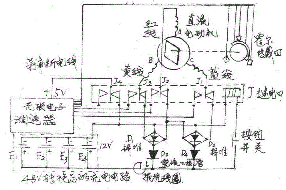
[0010] figure 1 It is the working principle diagram of "one machine with two uses". The basic function of the newly added components in the figure: the function of the J relay is to change the working state of the motor, that is, the state of the motor or the state of the generator. The function of the push button switch is to accept the control of the governor handle to energize or de-energize the J relay coil. The role of D1 and D2 bridge stacks is to rectify the pulsed alternating current into pulsed direct current. The functions of D3 and D4 are mainly to isolate the electric energy of the charged battery pack from backflow, and also to perform secondary rectification. The role of L is to match and filter the load circuit. The working process of the motor circuit; it first requires the speed control handle to release the pressure to let the button switch pop up, connect the relay coil to form a energization circuit, achieve circuit conversion, and connect with the three...


PUM


Abstract

The invention discloses a self-charging electromobile developed on the basis of 'dynamic-type electromobile charger' which is also an invention of the applicant. The dynamic-type electromobile charger cannot truly solve the actual problem that an electromobile cannot travel a long distance due to limiting of electric quantity of a battery, and the electromobile utilizes wind power to generate electricity, so that the size of a double-screw fan cannot be too large; the double-screw fan is limited by a mounting position, so that utilizing the double-screw fan to charge an aluminum acid battery is limited, and obviously the electromobile cannot replace a fuel-oil-engine automobile unless obvious breakthroughs are made on a super-capacitor battery pack matched with the electromobile for use. A self-drive direct-current motor of the electromobile is invented by the applicant to serve as a power generator, and a function of one-machine-two-purpose is realized. Actual application results in recent mouths show that the power generator is excellent in actual power generation effect, higher in power efficiency and capable of increasing the travel distance of the electromobile by about 1.5 times, and all electric performance of the electromobile are normal. Electric quantity of the electromobile can be charged more than 98% by arranging the super-capacitor battery pack, and due to self-power-generating equipment and quick-energy-storage equipment, realization of long-distance travel of the electromobile is possible, and low carbon on the earth can be realized.

Description

technical field [0001] The invention relates to a "self-charging electric vehicle". Background technique [0002] In order to effectively solve the technical problem of power renewing on the way to the vehicle, I applied for an invention patent on January 18, 2012. The name is "Dynamic Charger for Electric Vehicles", and the invention patent number is 201210014432.9. The invention patent mainly applied wind power generation technology, and the "double helical fan" invented and designed by me basically realized the function of charging the lead-acid battery pack of electric vehicles while driving. But it still can't really realize how far you want to run like a car, and there is no limit to where you want to go, and it still can't get rid of the actual use range that can only go around in the urban area. It will have a good and obvious effect unless it is equipped with a "super capacitor battery pack". In order to realize the "self-charging electric vehicle" more effectivel...

Claims


Application Information

Patent Timeline
Patent Type & Authority Patents(China)
IPC IPC(8): B60L11/18
CPCY02T10/70
Inventor 朱建荣
Owner 朱建荣
Why Eureka
Try Eureka