Diesel engine timing locating method

A diesel engine and positioning pin hole technology, which is applied to mechanical equipment, engine components, machines/engines, etc., can solve the problems that affect the assembly cycle and production efficiency, and the timing positioning accuracy is not high, so as to achieve easy operation, avoid errors, and simplify assembly The effect of craft

Inactive Publication Date: 2013-12-04
东风朝阳朝柴动力有限公司
View PDF4 Cites 12 Cited by
  • Summary
  • Abstract
  • Description
  • Claims
  • Application Information

AI Technical Summary

Problems solved by technology

The timing positioning accuracy of this method is not high, and there are human measurement errors. In addition, when assembling the transmission gears, the timing marks of each gear need to be matched and assembled, which seriously affects the assembly cycle and production efficiency.

Method used


Image

  • Diesel engine timing locating method

Examples


Embodiment Construction

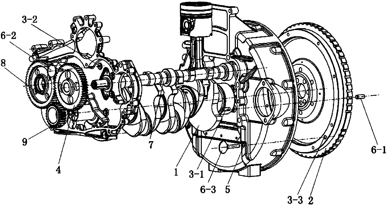
[0012] The principles and methods of the present invention will be described in detail below in conjunction with the accompanying drawings and through embodiments. The method for positioning the timing of the diesel engine is: a first positioning pin hole 3-1 is provided on the crankshaft 1 and the flywheel 2; a second positioning pin hole 3-2 is provided on the camshaft gear 4 and the gear chamber; There is a third positioning pin hole 3-3 on the flywheel; timing positioning of the engine camshaft and crankshaft is carried out through the following steps:

[0013] (1) The crankshaft and flywheel are positioned through the first column pin 6-1, and the flywheel is embedded in the flywheel housing;

[0014] (2) Insert the second pin 6-2 through the camshaft gear into the second positioning pin hole on the gear chamber;

[0015] (3) At the rear end of the engine, insert the third column pin 6-3 through the flywheel housing into the third positioning pin hole 3-3 of the flywheel...


PUM


Abstract

The invention discloses a diesel engine timing locating method. The phase relation among an engine cam shaft, a crankshaft and a first cylinder is measured in advance, three locating pin holes are designed, and timing location is completed through the following four steps that the crankshaft and a flywheel are located through a first pin; a second pin penetrates through a cam shaft gear and is inserted into a second locating pin hole in a gear chamber; a third locating pin penetrates through a flywheel shell and is inserted into a third locating pin hole in the flywheel through the rear end of the engine, so that the cam shaft and the crankshaft opposite to the cam shaft in position are fixed on the upper dead center of the first cylinder; a crankshaft gear and an idler gear are installed, and meshing marks are arranged among the idler gear, the crankshaft gear and the cam shaft gear. According to the diesel engine timing locating method, timing location is very easy and convenient, operation is easy, and errors of determination of the upper dead center of the first cylinder caused by manual timing are avoided. By means of matching between the locating pins and the pin holes, the step that common gear assembly needs alignment of the meshing marks is omitted, the assembly process is simplified, production efficiency is improved, and the application effect is very good.

Description

technical field [0001] The invention belongs to engine structure technology, and in particular relates to a timing positioning system for diesel engine assembly and maintenance. Background technique [0002] With the continuous improvement of engine technology and the strict requirements of society for environmental protection, domestic and foreign automobile manufacturing industries have higher and higher requirements for the power, economy and emission of engines, which requires continuous improvement of engine processing and assembly. level etc. In order to reduce particulate matter emissions and improve engine efficiency, most diesel engines currently use high-pressure common rail technology. This technology first requires accurate timing and positioning of the engine during assembly, so as to adapt to the precise control of the fuel injection time and fuel injection of the injector by the electronic control unit. Quantity, and valve timing control the intake and exhaus...

Claims


Application Information

Patent Timeline
Patent Type & Authority Applications(China)
IPC IPC(8): F01L1/344
Inventor 董立明赵霄鹏孙超张晓杰
Owner 东风朝阳朝柴动力有限公司
Why Eureka
Try Eureka