
Novel high-efficiency thermionic power supply

A thermionic, high-temperature heat source technology, used in electrical components, generators/motors, generators that convert kinetic energy into electrical energy, etc., can solve the problems of complex power supply structure and operating conditions, small power generation capacity of a single power supply, and shrinking application fields. , to achieve the effect of inhibiting escape and transfer, accelerating escape and transfer, and improving the utilization rate of heat energy

Inactive Publication Date: 2013-12-04
张维国
View PDF0 Cites 7 Cited by
  • Summary
  • Abstract
  • Description
  • Claims
  • Application Information

AI Technical Summary

Problems solved by technology

Based on its working principle, the existing thermionic power supply requires that the work function of the emitter electrode is relatively large, while the work function of the receiver electrode is relatively small. The temperature and pressure of the cesium vapor between the electrodes have a specific control range, and most of the heat is lost through the discharge of the receiver electrode; The thermoelectric conversion efficiency of the existing thermionic power supply is about 10%, the power generation capacity of a single power supply is small, the output voltage is low, the power supply structure and operating conditions are complicated and the cost is high, and there are many problems hindering commercial application, so this kind of power supply has been used for many years. Failed to promote, and even the application field is gradually shrinking; the design of the new thermionic power supply can change this situation, and will replace the existing power generation equipment in many fields

Method used


Image

  • Novel high-efficiency thermionic power supply
  • Novel high-efficiency thermionic power supply
  • Novel high-efficiency thermionic power supply

Examples


Embodiment Construction

[0019] The present invention will be further described with reference to the accompanying drawings.

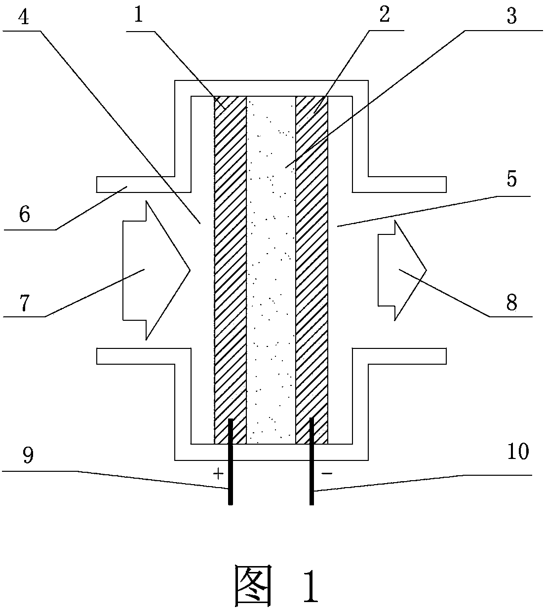
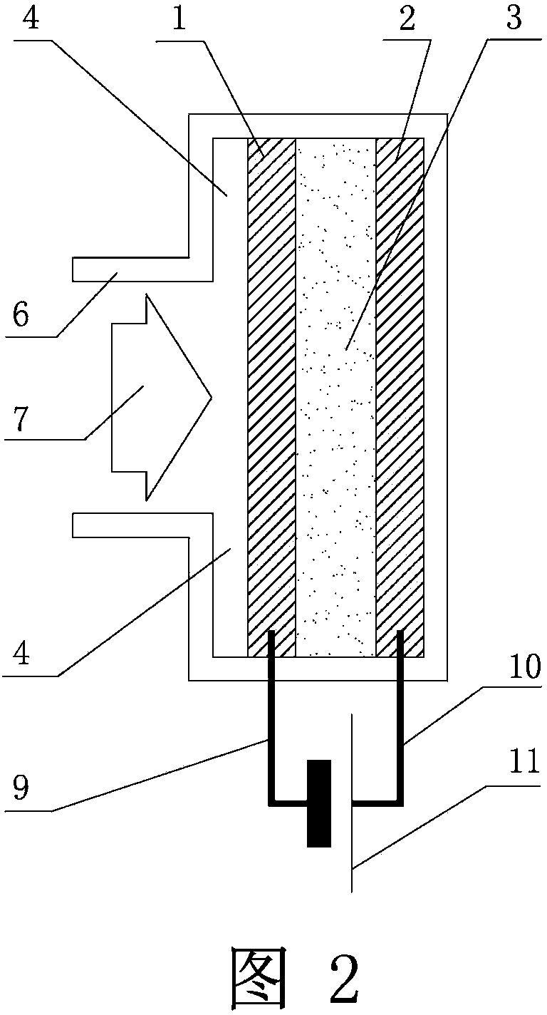
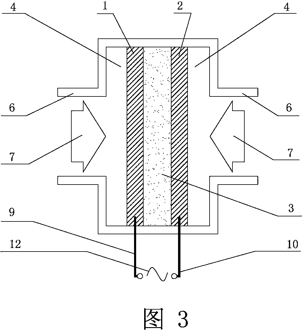
[0020] DC output scheme: the new high-efficiency thermionic power supply includes an emitter 1, a receiver 2, a high-temperature heat chamber 4 and a high-temperature heat source 7, and is characterized in that: the emitter 1 is made of a thermionic emission material whose melting point is higher than the temperature of the high-temperature heat source 7, The receiving electrode 2 is made of non-thermal electron emission material whose melting point is higher than the temperature of the high-temperature heat source 7, and the work function of the material of the emitting electrode 1 is less than or equal to the work function of the material of the receiving electrode 2; Inside, the heat-insulating shell 6 is closed, the emitter 1 and the receiver 2 are in the same high-temperature thermal cavity 4, the gap between the emitter 1 and the receiver 2 is between 0.01 and 2 mm, and t...


PUM


Abstract

The invention relates to a novel high-efficiency thermionic power supply. The novel high-efficiency thermionic power supply is characterized in that an emitting electrode (1) is made of thermionic emitting material of which the melting point is higher than the temperature of a high-temperature heat source (7); a receiving electrode (2) is made of non-thermionic emitting material of which the melting point is higher than the temperature of the high-temperature heat source (7); the emitting electrode (1) and the receiving electrode (2) are arranged in a heat-insulating casing (6) and are located in a same high-temperature heat chamber (4); the emitting electrode (1) and the receiving electrode (2) are connected with an electric pump direct current power supply (11) in series through a lead (9) and a lead (10); the thermionic emission of the emitting electrode (1) is caused by heating the emitting electrode (1) through the high-temperature heat source (7), so that the electromotive force of the receiving electrode (2) is higher than the electromotive force of the emitting electrode (1) and further extra power is provided for thermions to move to the receiving electrode (2); the thermions fly to the receiving electrode (2) under the push of the driving electromotive force of the receiving electrode (2) and an induced electric field of the electric pump direct current power supply (11), pass through a clearance between the two electrodes, and are captured on the receiving electrode (2). According to the novel high-efficiency thermionic power supply, various energy sources, such as nuclear energy, heat energy and light energy, can be converted into ionization energy as much as possible.

Description

technical field [0001] The thermionic power supply of the present invention belongs to the technical field of static thermoelectric conversion devices, and is applicable to fields such as nuclear energy, thermal power, and solar power generation; Firepower, solar energy and other energy sources serve military equipment, civilian power, nuclear power, aerospace power and other fields. Background technique [0002] Thermionic energy converter is a kind of static power generation power supply that uses the thermionic emission phenomenon on the metal surface to provide electrical energy. It does not need mechanical rotating parts to directly convert thermal energy into electrical energy. It has been successfully applied to space technology and nuclear-powered submarines, and it has recently been used as the front stage of thermal power generation systems. The structure of the current thermionic power supply is: a high-temperature heat source heats an emitter made of a material...

Claims


Application Information

Patent Timeline
Patent Type & Authority Applications(China)
IPC IPC(8): H02N3/00
Inventor 张维国
Owner 张维国
Learn More