Control system special for down-the-hole drill carriage
What is Al technical title?
Al technical title is built by PatSnap Al team. It summarizes the technical point description of the patent document.
A control system and down-the-hole drilling technology, which is applied to the automatic control system of drilling, the driving device for drilling in the wellbore, and the drill pipe. To achieve the effect of improving operation performance, simplifying working conditions and maintaining constant load
Active Publication Date: 2014-08-20
ZHEJIANG JICHAO AUTOMATION TECH
View PDF5 Cites 0 Cited by
Summary
Abstract
Description
Claims
Application Information
AI Technical Summary
This helps you quickly interpret patents by identifying the three key elements:
Problems solved by technology
Method used
Benefits of technology
Problems solved by technology
One is to use the form of motor drive, through which the motor is connected to the reducer or the hydraulic system to drive the down-the-hole drill to work; this drive mode is simple to control and stable in work, but it is difficult to realize self-propelled due to the limitation of the power supply device.
Another hydraulic drive system that uses an internal combustion engine to connect the drill bit and the traveling device through the internal combustion engine; this driving method realizes the self-propelled equipment, but due to complex working conditions and frequent changes in the load of the internal combustion engine, the control system is complicated and the stability decreases
At present, the new type of down-the-hole drilling rig uses internal combustion engine to generate electricity, and then uses electric power to drive the drill bit and traveling device. This driving form has the advantages of the above two driving forms, but it puts forward higher requirements for the control system.
Method used
Image
Click on the blue label to locate the original text in one second.
Reading with bidirectional positioning of images and text.
Examples
Embodiment approach
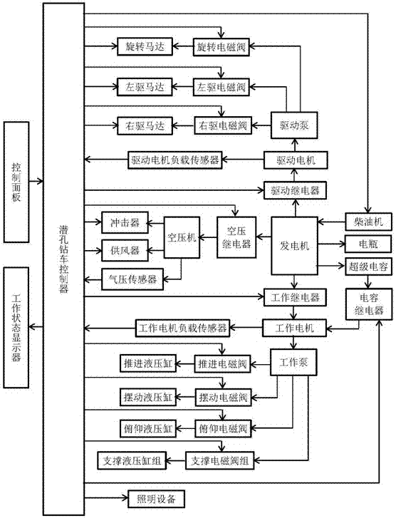
[0009] Such as figure 1 As shown, the special control system for down-the-hole drilling rig includes down-the-hole drilling rig controller, control panel, working status display, rotary motor, rotary solenoid valve, left drive motor, left drive solenoid valve, right drive motor, right drive solenoid valve, Drive pump, drive motor load sensor, drive motor, drive relay, impactor, air supply device, air pressure sensor, air compressor, air pressure relay, generator, diesel engine, battery, super capacitor, working relay, capacitor relay, working motor Load sensor, working motor, capacitor relay, propulsion hydraulic cylinder, propulsion solenoid valve, working pump, swing hydraulic cylinder, swing solenoid valve, pitch hydraulic cylinder, pitch solenoid valve, support hydraulic cylinder group, support solenoid valve group, lighting equipment; submersible The controller of the drilling rig is connected with the working status display, diesel engine, rotary motor, rotary solenoid v...
PUM
Abstract
The invention discloses a control system special for a down-the-hole drill carriage. The control system special for the down-the-hole drill carriage comprises a down-the-hole drill carriage controller, a control panel, a working condition displayer, a rotary motor, a rotary solenoid valve, a left drive motor, a left drive solenoid valve, a right drive motor, a right drive solenoid valve, a drive pump, a drive motor load sensor, a drive motor, a drive relay, an impactor, an air supply device, a baroceptor, an air compressor, an air compressor relay, a generator, a diesel engine, a storage battery, a super-capacitor, a working relay, a capacitance relay, a working motor load sensor, a working motor, an impelling hydraulic cylinder, an impelling solenoid valve, a working pump, a swinging hydraulic cylinder, a swinging solenoid valve, a pitching hydraulic cylinder, a pitching solenoid valve, a supporting hydraulic cylinder group, a supporting solenoid valve group and a lighting device. According to the control system special for the down-the-hole drill carriage, whole electro-hydraulic drive of the down-the-hole drill carriage is realized. Besides, the down-the-hole drill carriage has the advantages of being stable in diesel engine load, simple in control system, simple in mechanical structure, small in energy loss, large in output force, and high in drilling efficiency.
Description
technical field [0001] The invention relates to a control system of a drilling rig, in particular to a special control system for a down-the-hole drilling rig. Background technique [0002] Down-the-hole drilling is engineering equipment used to drill holes in rocks. It can be used to drill rock anchor holes, anchor holes, blast holes, grouting holes, etc. in urban buildings, railways, highways, rivers, hydropower and other projects. Drilling construction. With the increasing demand for resources, many mines are in urgent need of the key equipment of the mining process - down-the-hole drilling rigs. At the same time, in order to improve drilling efficiency, thereby shortening the moving time of drilling equipment, increasing the number of drilling holes per unit time, and thereby improving production efficiency, self-propelled down-the-hole drilling rigs have received more and more attention. [0003] At present, there are mainly two driving forms of down-the-hole drilling...
Claims
Application Information
Patent Timeline
Application Date:The date an application was filed.
Publication Date:The date a patent or application was officially published.
First Publication Date:The earliest publication date of a patent with the same application number.
Issue Date:Publication date of the patent grant document.
PCT Entry Date:The Entry date of PCT National Phase.
Estimated Expiry Date:The statutory expiry date of a patent right according to the Patent Law, and it is the longest term of protection that the patent right can achieve without the termination of the patent right due to other reasons(Term extension factor has been taken into account ).
Invalid Date:Actual expiry date is based on effective date or publication date of legal transaction data of invalid patent.