Semi-automatic electrode cap surfacing machine

A technology of electrode caps and surfacing machines, applied in welding equipment, auxiliary welding equipment, welding/cutting auxiliary equipment, etc., can solve the problems of difficulty in meeting the requirements of industrialized enlarged production, unsatisfactory surfacing efficiency, and melting efficiency Major problems, to achieve the effect of reducing the intensity of surfacing welding operations, saving labor resources, and reducing labor costs

Inactive Publication Date: 2013-12-11
苏州飞泰精工科技有限公司
View PDF17 Cites 5 Cited by
  • Summary
  • Abstract
  • Description
  • Claims
  • Application Information

AI Technical Summary

Problems solved by technology

[0008] The fused titanium carbide on the surface of the electrode cap mentioned above is surfacing welding titanium carbide (hereinafter the same), in view of the fact that there is no such method used to fused titanium carbide on the end surface of the point electrode cap in the published patents and non-patent literature so far. Due to the technical inspiration of the special device, workers usually hold the welding torch to fuse the transition metal rod (rod-shaped) clamped on the welding torch to the end face of the electrode cap. However, due to the special shape of the electrode cap (like a hollow one The shape and size of the bullet with a conical blind hole is small), so it is very troublesome to clamp it reliably unless a complex and unique fixture device is used; If the electrode cap is reliably clamped, the worker needs to make the welding torch frequently move 360° around the electrode cap (circling action) during the melting process, resulting in high work intensity for the worker and unsatisfactory surfacing efficiency; Also because the longer the process of clamping and releasing the electrode cap, the greater the impact on the melting efficiency, so it is difficult to meet the requirements of industrial scale-up production; and because in order to adapt to the requirements of industrial production, more piles have to be invested Welders, which not only cause waste of labor resources, but also lead to increased manufacturing costs

Method used


Image

  • Semi-automatic electrode cap surfacing machine
  • Semi-automatic electrode cap surfacing machine

Examples


Embodiment Construction

[0023] In order to enable the examiners of the patent office, especially the public, to understand the technical essence and beneficial effects of the present invention more clearly, the applicant will describe in detail the following in the form of examples, but none of the descriptions to the examples is an explanation of the solutions of the present invention. Any equivalent transformation made according to the concept of the present invention which is merely formal but not substantive shall be regarded as the scope of the technical solution of the present invention.

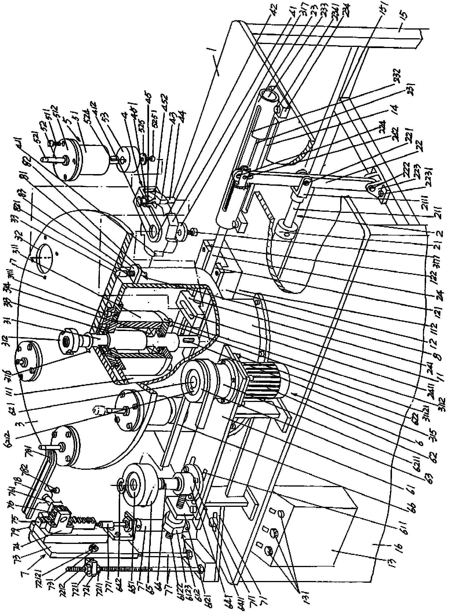
[0024] In the following descriptions, all orientation concepts such as up, down, left, right, front, and back are based on the current figure 1 As far as the positional state shown is concerned, it should not be understood as a specific limitation of the solution of the present invention.

[0025] See figure 1 , provides a workbench 1, the shape of the workbench 1 is a rectangular shape, the present embodime...


PUM


Abstract

The invention relates to a semi-automatic electrode cap surfacing machine, and belongs to the processing machinery of spot welding electrodes. The semi-automatic electrode cap surfacing machine comprises a worktable, a pawl shaft driving mechanism, a rotary table, a rotary table shaft driving mechanism, a group of electrode cap pivotal supporting mechanisms, a power transmission mechanism and an automatic electrode cap driving mechanism, wherein a cylinder seat and a guide rail seat are fixedly arranged on the worktable, and one side of the cylinder seat forms a push rod abdicating cavity; the guide rail seat is positioned in a cylinder seat cavity, and a protective plate is arranged at the front side of the worktable; an electric control box is arranged at the left end of the protective plate, and the pawl shaft driving mechanism is arranged on the worktable; the rotary table shaft is fixedly arranged at the center of the rotary table, and the rotary table shaft driving mechanism is connected with the lower end of the rotary table shaft; the group of electrode cap pivotal supporting mechanisms are arranged around the edge part of the rotary table in the circumferential direction at intervals, and the power transmission mechanism and the automatic electrode cap driving mechanism are arranged on the worktable; and the power transmission mechanism comprises a motor support, a motor, a driving transmission wheel, a driven transmission axle, a driven transmission wheel and a conveyor belt. The semi-automatic electrode cap surfacing machine has the advantages of simple structure, low work intensity, ideal automation effect, reduction in human input, and low labor cost, and ensures the movement effect of the electrode cap pivotal supporting mechanism.

Description

technical field [0001] The invention belongs to the technical field of spot welding electrode processing machinery, and in particular relates to a semi-automatic electrode cap overlay welding machine. Background technique [0002] The semi-automatic concept of the semi-automatic electrode cap surfacing machine mentioned above refers to: the operator manually places the electrode cap to be surfacing on the electrode cap surfacing machine, and manually adjusts the electrode in the rotating state. The end face of the cap is surfacing, and other actions such as rotating the electrode cap and driving away the electrode cap after surfacing are all automatically completed by the electrode cap surfacing machine. [0003] The electrode cap mentioned above is the spot welding electrode, which is widely used in various welding equipment such as spot welding machines, resistance welding pliers, etc. Under the condition of strength, there is a difference in the resistance calorific valu...

Claims


Application Information

Patent Timeline
Patent Type & Authority Applications(China)
IPC IPC(8): B23K37/00
Inventor 顾祖良
Owner 苏州飞泰精工科技有限公司
Why Eureka
Try Eureka