Flexible substrate foil roll-to-roll conveyer and conveying method

A flexible substrate and conveying device technology, applied in the field of vacuum coating, can solve the problems of internal defects of deposited films, substrate foil flutter, low tensile performance, etc., to reduce equipment length and space requirements, less tension adjustment mechanism, convenient The effect of system upgrade

Inactive Publication Date: 2013-12-11
胡增鑫
View PDF7 Cites 7 Cited by
  • Summary
  • Abstract
  • Description
  • Claims
  • Application Information

AI Technical Summary

Problems solved by technology

The problems caused by this may include: a) greatly increasing the size of the equipment and thus increasing the cost; b) in order to ensure stable transportation and uniform tension distribution, it is necessary to add multiple tension adjustment rollers, steering mechanisms and winding mechanisms, resulting in complex equipment structures , high cost, and high failure rate; c) The accumulated resistance caused by excessively long transport distance and excessive turning requires the winding mechanism to increase the output of rotational torque, which may cause excessive The tensile deformation of the deposited film can cause internal defects in the deposited film and even the substrate itself to break
[0007] 2. For the "one-dimensional" roll-to-roll delivery method used in the longer flat-plate coating device, if the span of the turning rollers at both ends is too large, the tension of the substrate foil in this area cannot be guaranteed to be sufficient. Foil will "chatter" and not pass smoothly through the coating area, resulting in poor coating quality
[0008] 3. For the "two-dimensional" transportation method with multiple turns, if there is an "S" turn, one of the guide wheels must have a coating surface that contacts the flexible substrate foil, and the friction generated by the rotation may damage the film

Method used


Image

  • Flexible substrate foil roll-to-roll conveyer and conveying method
  • Flexible substrate foil roll-to-roll conveyer and conveying method
  • Flexible substrate foil roll-to-roll conveyer and conveying method

Examples


Embodiment 1

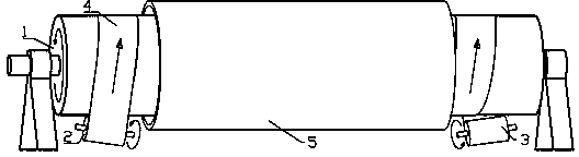
[0038] figure 1 It is a schematic diagram of Embodiment 1 of the present invention, illustrating the working principle of the conveying device and conveying method of the present invention.

[0039] The flexible substrate foil 4 unwound by the unwinding mechanism 2 is wound from one end of the winding mechanism 1 along a counterclockwise spiral, reaches the other end of the roller after several weeks, and is fixed to the winding mechanism 3 . With the rotation of the winding mechanism 1, the unwinding mechanism 2 and the winding mechanism 3 (the direction is shown in the figure), the flexible substrate foil 4 is continuously rolled out from the unwinding mechanism 2, and rotates forward along the helical line (the direction is as shown in the figure). As shown in the figure), it is finally involved in the winding mechanism 3 to complete the entire roll-to-roll delivery process.

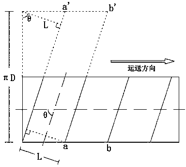
[0040] Figure 5 It is a schematic diagram of the geometric relationship of Embodiment 1 of the...

Embodiment 2

[0047] figure 2 It is a schematic diagram of Embodiment 2 of the present invention.

[0048] On the basis of Embodiment 1, take the cylindrical shape around the winding mechanism 1 as an example to represent the available coating / processing area 5 of the present invention. According to different coating / processing technology requirements and device types, the shape of the processing area can be A rectangular plate, an arc plate or other forms surrounding the winding mechanism 1.

[0049]

Embodiment 3

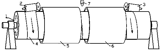
[0051] image 3 It is a schematic diagram of Embodiment 3 of the present invention.

[0052] In Embodiment 3, the flexible substrate foil 4 is wound along a clockwise helical line, and the corresponding rotation directions of the winding mechanism 1 , the unwinding mechanism 2 and the winding mechanism 3 are shown in the figure. At the same time, the coating / processing area is divided into two sections: coating / processing area 5 and coating / processing area 6, so that different types of coating / processing technologies can be carried out in stages without complex steering mechanisms. Necessary isolation devices (not shown in the figure) can be set in the middle area, or the probe 7 of an online thin film detection and analysis instrument can be set.

[0053]


PUM


Abstract

The invention provides a flexible substrate foil roll-to-roll conveyer and conveying method, which are used in vacuum coating equipment and can enlarge a processing region area during a stable material conveying process so as to improve equipment productivity. According to the invention, flexible substrate foil is tightly jointed to and wound on the outer surface of the roller of a winding mechanism in a spiral way, the flexible substrate foil is driven to rotate to advance in a screw type through the rotation of the winding mechanism, through coordination with actions of an unwinding mechanism and a winding mechanism, the flexible substrate foil roll-to-roll conveying process is achieved. A coating or processing device can be arranged in a space on the circumference of the middle part of the winding mechanism according to requirements. The interior of the winding mechanism is provided with a device with heating and cooling functions, or the winding mechanism serves as a ground joint, and the winding mechanism not only has a function of providing a power source for conveying material, but also has a function of controlling the temperature of the flexible substrate foil. According to the invention, parallel tandem arrangement can be performed conveniently, and the purpose of adjusting procedures or expanding productivity can be achieved.

Description

technical field [0001] The invention relates to the field of vacuum coating, in particular to a roll-to-roll conveying device and a conveying method in continuous thin film material deposition equipment implemented on a flexible substrate foil by various vacuum coating methods. Background technique [0002] Roll-to-Roll (Roll-to-Roll) vacuum coating equipment for continuous deposition of semiconductor materials, metal materials or organic materials on flexible substrate foils (such as metal foils, plastic films, etc.) The special processing of thin films (such as annealing, etching, passivation, laser scribing, etc.) is widely used in the mass production of flexible photovoltaic devices, flexible display devices, flexible semiconductor light-emitting devices and flexible integrated circuits. [0003] The conveying device in the roll-to-roll vacuum coating equipment or other processing equipment for flexible substrates usually includes a winding mechanism, an unwinding mechan...

Claims


Application Information

Patent Timeline
Patent Type & Authority Applications(China)
IPC IPC(8): C23C14/56
Inventor 胡增鑫
Owner 胡增鑫
Why Eureka
Try Eureka