Supercharge Your Innovation With Domain-Expert AI Agents!

Four-order transmission error curve design method based on spiral bevel gears

A technology of spiral bevel gear and transmission error, applied in the direction of components with teeth, belts/chains/gears, mechanical equipment, etc., can solve the problems of reducing the impact of tooth change, poor transmission performance, and difficulty in expanding the angle.

Inactive Publication Date: 2013-12-11
NORTHWESTERN POLYTECHNICAL UNIV
View PDF6 Cites 5 Cited by
  • Summary
  • Abstract
  • Description
  • Claims
  • Application Information

AI Technical Summary

Problems solved by technology

When two tooth pairs mesh, there will be three gear change points (for example, 1, 2, 3), but the gear change point No. 2 is in the ascending section of one curve and the descending section of the other curve, so the clip surrounded by the tangent The angle cannot be greater than the predetermined 135°, and the impact is too large; the concave-convexity of a certain curve where the gear-changing point 1 and the gear-changing point 3 are located is about to change. It is very difficult to enlarge the angle
Therefore, the transmission performance reflected by the Stadtfeld-type transmission error curve is still not good enough
[0014] The design of the Stadtfeld-type fourth-order transmission error curve aims to transform a large impact generated when changing gears in the parabolic transmission error curve into three small impacts, but virtually increases the number of gear changes and impact frequency, making the same When a tooth pair meshes, a total of six gear changes are required from the tooth root to the tooth top. In this way, compared with the second-order transmission error curve, Stadtfeld’s fourth-order transmission error curve significantly reduces the impact of tooth change, but there is still room for further improvement

Method used


Image

  • Four-order transmission error curve design method based on spiral bevel gears
  • Four-order transmission error curve design method based on spiral bevel gears
  • Four-order transmission error curve design method based on spiral bevel gears

Examples


Embodiment Construction

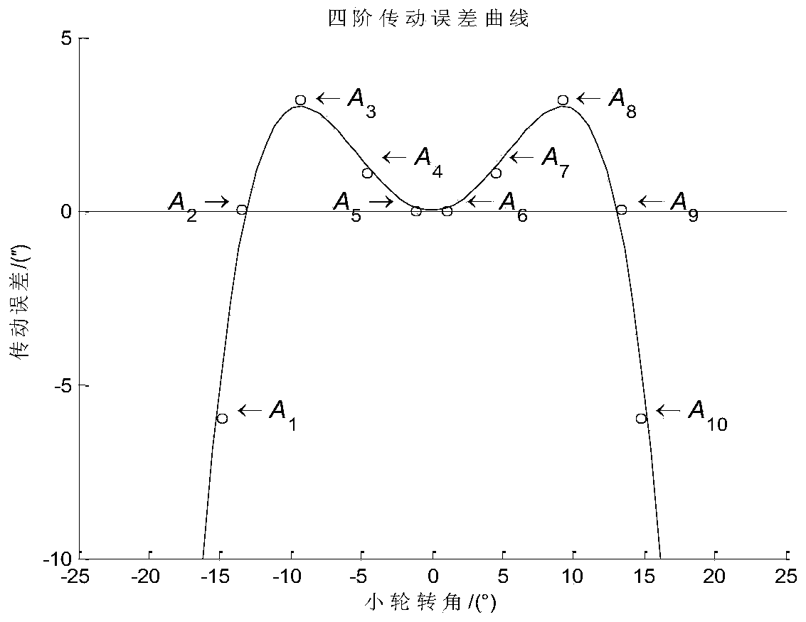
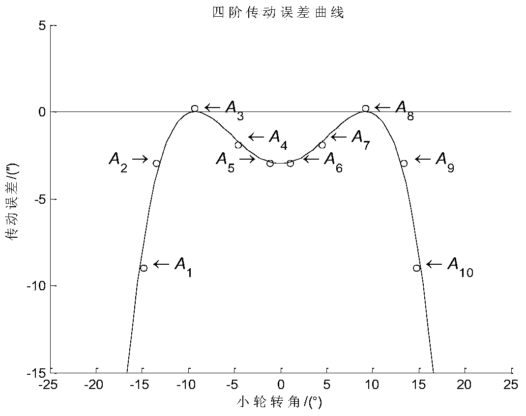
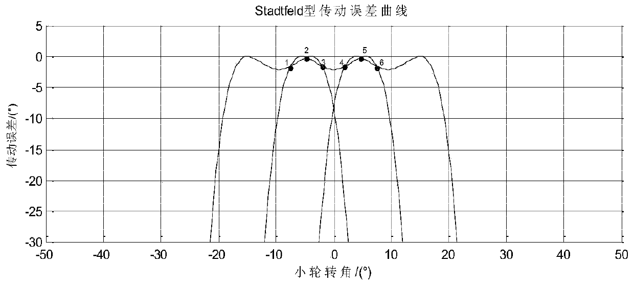
[0067] refer to Figure 1-6 . The concrete steps of the fourth-order transmission error curve design method based on the spiral bevel gear of the present invention are as follows:

[0068] 1. The spiral bevel gear is a point contact local conjugate transmission, and the transmission error is defined as

[0069]

[0070] In the formula, is the actual turning angle of the wheel, is the actual turning angle of the small and large wheel; Indicates the actual rotation angle of the small wheel and the large wheel when the reference point of the tooth surface meshes; z 1 ,z 2 The number of teeth of the small wheel and the big wheel respectively. is the rotation angle of the bull wheel when it meshes with the reference point, is the rotation angle of the small wheel when meshing relative to the reference point, is the nominal rotation angle of the bull wheel determined according to the nominal transmission ratio. Among them, the relative rotation angle of the big whe...


PUM


Abstract

The invention discloses a four-order transmission error curve design method based on spiral bevel gears. The method is used for solving the technical problem of teeth replacement impact in an existing four-order transmission error curve design method. According to the technical scheme, a transmission error equation is expanded into a four-order form at a tooth surface reference point according to a Taylor series, an expression of the rotation angle of driving gears when the driving gears are meshed relative to the reference point is extracted from the four-order Taylor series expansion equation, and an objective function of a two-order curve is established. An objective function of difference between control peak-to-peak values is established so that a transmission error curve of guide teeth and following-up teeth can be just obtained when a current gear transmission error curve horizontally moves towards the left or the right by the distance equal to a driving gear tooth pitch, namely, the distance between peaks of two adjacent transmission error curves is the distance equal to the driving gear tooth pitch at the moment, an interaction point just coincides with the maximum value point, the tangent line included angle at the interaction point approximates to 180 degrees, and vibration and impact in tooth replacement are eliminated.

Description

technical field [0001] The invention relates to a design method of a fourth-order transmission error curve, in particular to a design method of a fourth-order transmission error curve based on a spiral bevel gear. Background technique [0002] refer to Figure 1-4 . Spiral bevel gear is a very important transmission part in mechanical transmission. It has the characteristics of strong bearing capacity, stable transmission and high efficiency, so it is widely used in mechanical transmission fields such as aviation, aerospace, navigation and automobiles. The transmission performance of the spiral bevel gear is related to the transmission error curve and the tooth surface contact imprint, and the existence of the transmission error is one of the main factors of vibration, impact and noise in the transmission of the spiral bevel gear, which includes dynamic performance and strength performance Wait for a lot of information. From a dynamic point of view, vibration is caused by ...

Claims


Application Information

Patent Timeline
IPC IPC(8): F16H55/17
Inventor 刘光磊李德庚王乐赟
Owner NORTHWESTERN POLYTECHNICAL UNIV
Features
  • R&D
  • Intellectual Property
  • Life Sciences
  • Materials
  • Tech Scout
  • Unparalleled Data Quality
  • Higher Quality Content
  • 60% Fewer Hallucinations
Learn More