
Economical impedance measurement circuit

An impedance measurement and measurement loop technology, applied in the field of measurement circuits, can solve the problems of low penetration rate, high price, and narrow applicable population, and achieve the effects of simple production, low cost and stable performance

Inactive Publication Date: 2013-12-11
KUNSHAN AODELU AUTOMATION TECH
View PDF9 Cites 0 Cited by
  • Summary
  • Abstract
  • Description
  • Claims
  • Application Information

AI Technical Summary

Problems solved by technology

However, although the current impedance measuring instrument Q meter has high precision, it is expensive, the applicable population is narrow, and the popularization rate is low, especially for students in school. too expensive to afford

Method used


Image

  • Economical impedance measurement circuit
  • Economical impedance measurement circuit
  • Economical impedance measurement circuit

Examples


Embodiment Construction

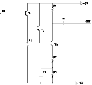
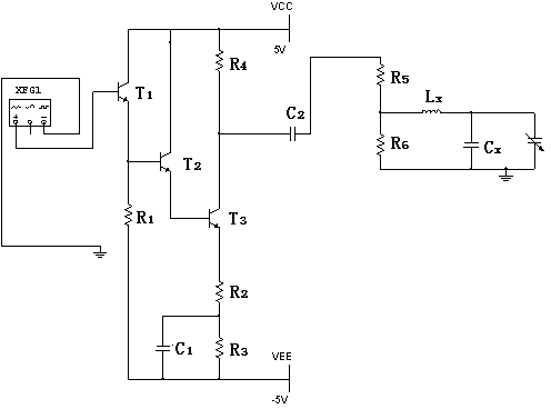
[0014] Such as figure 1 As shown, the present invention includes an economical impedance measurement circuit, including a signal source, a measurement circuit and a millivolt meter. The circuit also includes a follower, the input of the follower is connected with the output of the signal source, and the output of the follower is connected with the output of the signal source. The input end of the measurement circuit is connected, and the output end of the measurement circuit is connected with the millivoltmeter;

[0015] Such as figure 2 As shown, the follower includes a triode, the first triode T 1 The base of the first transistor T is connected to the output terminal of the signal source. 1 The emitter and the second transistor T 2 The bases of the transistors are connected, and the collectors of the two transistors are connected to positive voltage, the third transistor T 3 base of the second transistor T 2 The emitter is connected, the third transistor T 3 As the ou...


PUM


Abstract

The invention discloses an economical impedance measurement circuit. The economical impedance measurement circuit comprises a signal source, a main measurement circuit, a millivoltmeter and a follower, wherein the input end of the follower is connected with the output end of the signal source, the output end of the follower is connected with the input end of the main measurement circuit, and the output end of the main measurement circuit is connected with the millivoltmeter. The economical impedance measurement circuit has the advantages that needed materials can be obtained easily, manufacturing is simple, and cost is low. The economical impedance measurement circuit is applicable to people with low impedance measurement accuracy requirements and impedance comparison needed, and is particularly suitable for students. The performance of the economical impedance measurement circuit is stable.

Description

[0001] technical field [0002] The present invention relates to a measuring circuit, in particular to a circuit for measuring impedance. Background technique [0003] At present, multi-purpose and multi-range impedance measuring instruments can be used to measure the Q value of high-frequency inductors or resonant circuits, the inductance and distributed capacitance of inductors, the capacitance and loss angle of capacitors, the high-frequency dielectric loss of electrical materials, Effective parallel and series resistance of high-frequency circuits, characteristic impedance of transmission lines, etc. However, although the current impedance measuring instrument Q meter has high precision, it is expensive, the applicable population is narrow, and the popularization rate is low. Expensive and unaffordable. [0004] Therefore need a kind of new technical scheme to solve the above problems. Contents of the invention [0005] Purpose of the invention: In view of the probl...

Claims


Application Information

Patent Timeline
IPC IPC(8): G01R27/02
Inventor 郁彬
Owner KUNSHAN AODELU AUTOMATION TECH
Learn More