
Current monitoring circuit with accurate current-limit function

A current monitoring and accurate technology, applied in emergency protection circuit devices, circuit devices, emergency protection circuit devices for limiting overcurrent/overvoltage, etc., can solve the problem of increased short circuit protection power consumption and inability to achieve accurate output current limiting Protection and other issues, to achieve the effect of reducing assembly density, consistent parameters, and simplifying lines

Inactive Publication Date: 2013-12-11
NO 771 INST OF NO 9 RES INST CHINA AEROSPACE SCI & TECH
View PDF4 Cites 13 Cited by
  • Summary
  • Abstract
  • Description
  • Claims
  • Application Information

AI Technical Summary

Problems solved by technology

Due to the detection of the previous stage current, when the input voltage increases, the power consumption of the short circuit protection will increase exponentially, and the precise current limiting protection of the output current cannot be realized

Method used


Image

  • Current monitoring circuit with accurate current-limit function
  • Current monitoring circuit with accurate current-limit function
  • Current monitoring circuit with accurate current-limit function

Examples


Embodiment Construction

[0022] The present invention will be further described in detail below in conjunction with specific embodiments, which are for explanation rather than limitation of the present invention.

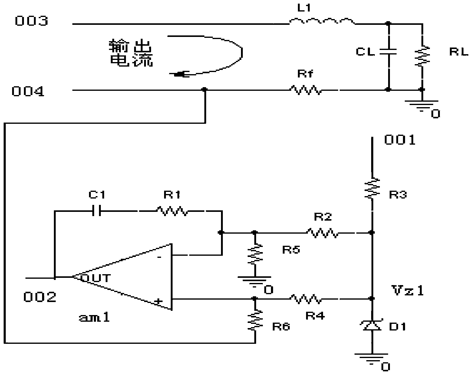
[0023] See figure 2 , The accurate current-limiting current monitoring circuit provided by the present invention includes an operational amplifier am1. The two input ports of the same direction input terminal and the reverse input terminal are respectively connected in series with symmetrical resistances, and the series resistance is passed through the voltage source port 001 The current-limiting resistor R3 and the voltage regulator tube Vz1 provide voltage; the reverse input terminal of the operational amplifier am1 is connected in series to the output terminal 002 of the operational amplifier am1 through the resistor R1 and the resistor C1, and the series symmetrical resistance of the operational amplifier am1 is also grounded; inductance L1 The output filter loop is formed with the capaci...


PUM


Abstract

The invention discloses a current monitoring circuit with the accurate current-limit function. The current monitoring circuit with the accurate current-limit function comprises an operational amplifier, wherein a forward input end and a reverse input end of the operational amplifier are respectively connected with a resistor in series, the resistors are symmetrical to each other, the reverse input end of the operational amplifier is connected to the output end of the operational amplifier in series through a resistor R1 and a capacitor C1, the symmetrical resistors which are connected with the operational amplifier in series are further in ground connection, an output filtering loop is formed by an inductor L1 and a capacitor CL, a load RL is connected to the capacitor CL in parallel, and is connected with a feedback resistor Rf in series, the feedback resistor Rf is connected to the forward input end of the operational amplifier am1 in series, and is used for carrying out sampling on current change signals of the output filtering loop, and the sampled current change signals are converted into voltage signals to be input into the forward input end of the operational amplifier. The current monitoring circuit with the accurate current-limit function directly detects output current signals, the output current signals are converted into the voltage signals through the resistors, and compared with reference voltage, the level of an enabling end can be reduced through output overturn of the operational amplifier, and short-circuit protection is achieved.

Description

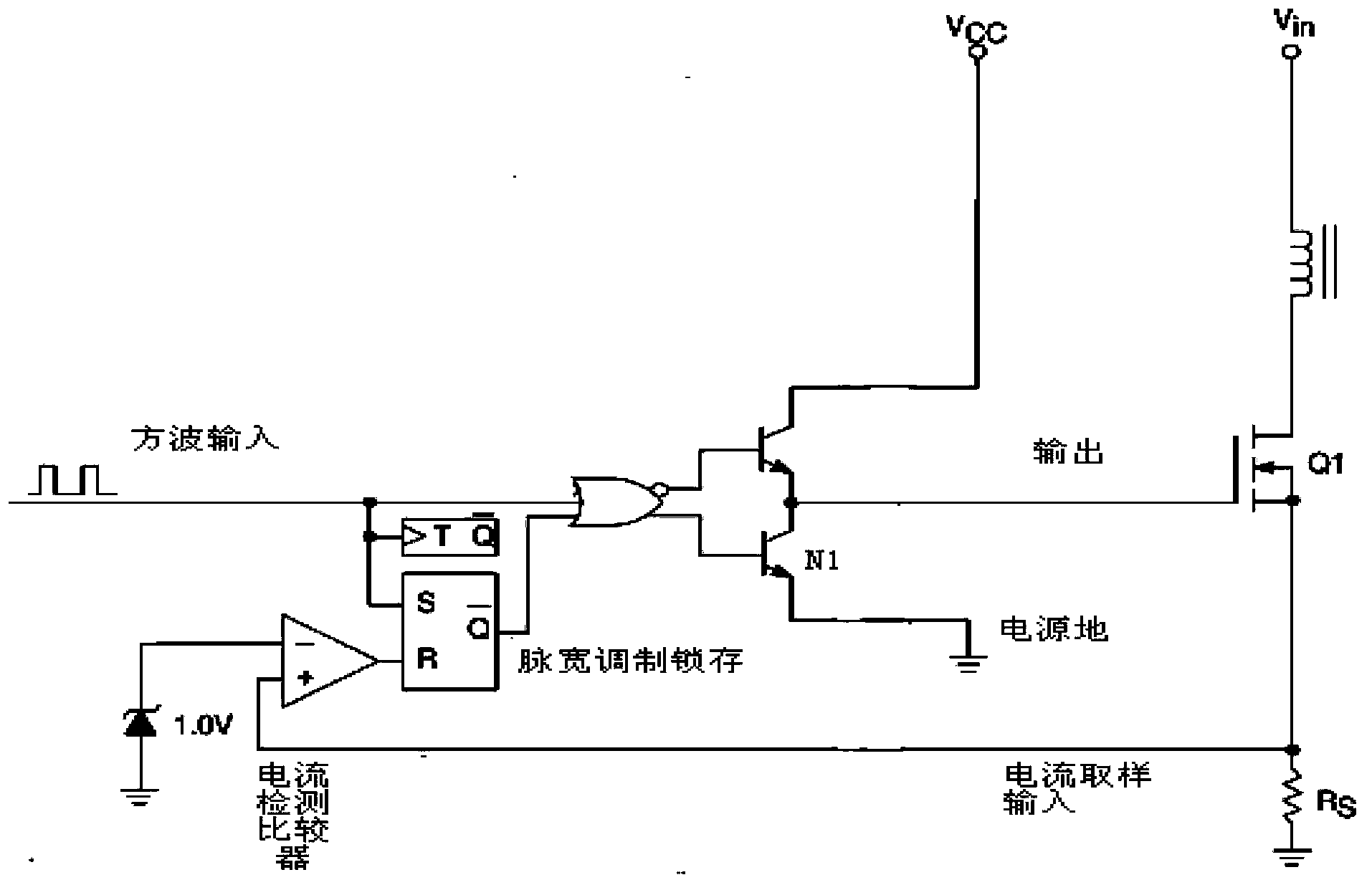
Technical field [0001] The invention belongs to the technical field of protection of power supply output short-circuit or over-current conditions, and relates to a current monitoring circuit with accurate current limiting. Background technique [0002] The current implementation method of power short-circuit protection is mainly the pre-input current sampling protection. [0003] The front-stage input current sampling protection is a protection method for input over power. Such as figure 1 As shown in the circuit, it realizes the output control of the PWM controller by collecting the primary peak current signal of the main transformer. When the current in the input line is too large, that is, when the peak current detection signal is greater than 1V, the current detection comparator will output a high level, which will cause the U1 (OR gate) output to be high, so that the transistor N1 is turned on and the output Pull it low to 0, the Q1 tube cannot be turned on, and finally the ...

Claims


Application Information

Patent Timeline
IPC IPC(8): H02H9/02
Inventor 王凯王英武王云王俊峰熊国兴
Owner NO 771 INST OF NO 9 RES INST CHINA AEROSPACE SCI & TECH
Learn More