
Method for controlling positive and negative commutating pulse power supply

A technology of pulse power supply and control method, which is applied in the control field of positive and negative commutation pulse power supply, can solve the problems of difficult, complex and huge control system, and achieve strong anti-interference ability, reduced complexity and high control precision. Effect

Active Publication Date: 2013-12-11
江西力源海纳科技股份有限公司
View PDF4 Cites 3 Cited by
  • Summary
  • Abstract
  • Description
  • Claims
  • Application Information

AI Technical Summary

Problems solved by technology

Since the forward and reverse commutation pulse power supply is much more complex than the ordinary rectifier power supply, the control system is also correspondingly large and complex
As the number of components in the control system increases, the volume of peripheral components also increases accordingly, and the distribution parameters have a greater impact. It is difficult to avoid mutual interference between components, thereby affecting the reliability of the equipment.
Since electroplating requires forward and reverse commutation pulse power frequency, duty cycle, positive pulse amplitude, and reverse pulse amplitude to be adjustable separately and at the same time, and to switch without disturbance, to avoid large output fluctuations from causing damage to electroplating equipment and electroplating products , it is difficult for ordinary control systems to realize

Method used


Image

  • Method for controlling positive and negative commutating pulse power supply
  • Method for controlling positive and negative commutating pulse power supply
  • Method for controlling positive and negative commutating pulse power supply

Examples


Embodiment Construction

[0026] The key of the present application is to improve the existing forward and reverse commutation pulse power supply, and propose the control method of the forward and reverse commutation pulse power supply of the present application on the basis of the improved forward and reverse commutation pulse power supply.

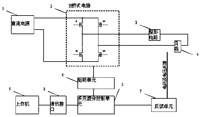
[0027] The improved positive and negative commutation pulse power supply of the present application includes a DC power supply, an H-bridge circuit, a shaping circuit, a load, a multivariate hybrid control unit, a drive unit, a feedback unit and a host computer, and the DC power supply is connected to the input end of the H-bridge circuit. The shaping circuit is connected to the output end of the H-bridge circuit after the load is connected in series. The multivariate hybrid control unit is connected to the control terminal of the H-bridge circuit through the drive unit. The load is connected to the multivariate hybrid control unit through the feedback unit. The mu...


PUM


Abstract

The invention discloses a method for controlling a positive and negative commutating pulse power supply. The method includes the steps that a multi-element mixed control unit is utilized to receive signals fed back by a feedback unit, and mixed control signals are calculated and synthesized according to the feedback signals; a driving unit drives a high-speed switch device of an H bridge circuit to form pulses according to the received mixed control signals; a shaping circuit conducts filtering reduction processing on the pulses output by the H bridge circuit, and the pulses with the required frequency, the duty ratio and the amplitude are acquired. According to the method for controlling the pulse power supply, a control system is simple in structure and high in control accuracy, anti-jamming capacity and response speed. The H bridge circuit outputs the frequency, the duty ratio and the amplitude of the pulses, and then the pulses are shaped by the shaping circuit, large fluctuation is prevented from being output to damage electroplating equipment and electroplating products, meanwhile, the frequency and the duty ratio of positive pulses and negative pulses, the amplitude of the positive pulses and the amplitude of the negative pulses can be adjusted respectively, and can be changed and switched in an undisturbed mode.

Description

technical field [0001] The technical field of power supply of the present application particularly relates to a control method of forward and reverse commutation pulse power supply. Background technique [0002] The rectified power supply provides direct current for electroplating of electronic circuit boards or surface electroplating of metal materials. With the increasing complexity, thickness, path density, and smaller aperture and path width, traditional DC plating becomes more and more difficult, and even leads to defective products. In order to balance the electroplating on the surface, especially in holes and micropores, the current density is forced to be reduced, but this will prolong the electroplating time, and the electroplating time has reached an unacceptable level. With the advent of positive and negative commutation pulse power and chemical composition suitable for the plating process, shortening the plating time has become a reality. Since the forward and ...

Claims


Application Information

Patent Timeline
Patent Type & Authority Applications(China)
IPC IPC(8): H02M9/02
Inventor 黄瑞炉张洪强黄海波丁少云
Owner 江西力源海纳科技股份有限公司
Learn More