OLED panel thinning device, thinning system and thinning method

A panel and corresponding position technology, applied in the field of OLED display, can solve the problems that the OLED substrate glass cannot be made thinner, reduce the thinning quality of the OLED panel, and easily produce pits on the OLED panel, so as to achieve easy promotion and use, simple operation, The effect of ensuring airtightness

Inactive Publication Date: 2016-03-16
SICHUAN CCO DISPLAY TECH
View PDF3 Cites 0 Cited by
  • Summary
  • Abstract
  • Description
  • Claims
  • Application Information

AI Technical Summary

Problems solved by technology

Limited by the manufacturing process, the thickness of the OLED substrate glass can no longer be made thinner. Therefore, the current thinning technology generally waits for the OLED panel to be packaged before etching and thinning.
Commonly used etching thinning technologies are mainly divided into immersion thinning and spray thinning. Immersion thinning refers to the method of soaking multiple encapsulated OLED panels in etching solution for a certain period of time to achieve thinning. , its disadvantage is that the etchant of the OLED panel is likely to cause contamination of the etching solution, and the contaminated etching solution will reduce the thinning quality of the OLED panel to be etched later; spray thinning refers to the use of uniform flow etching This method overcomes the reduction in thinning quality caused by etching solution contamination, but in this method, affected by the position of the nozzle and the size of the OLED panel, the etched OLED panel is prone to pits and It is difficult to achieve the effect of uniform thickness of the panel
In addition, immersion thinning and spray thinning are only suitable for thinning small-sized OLED panels. When OLED panels are advanced to large sizes, these two technical solutions are difficult to connect with the front and rear processes and difficult to achieve automation.

Method used


Image

  • OLED panel thinning device, thinning system and thinning method
  • OLED panel thinning device, thinning system and thinning method
  • OLED panel thinning device, thinning system and thinning method

Examples


Embodiment Construction

[0038] In order to make the object, technical solution and advantages of the present invention clearer, the present invention will be further described in detail below in conjunction with the accompanying drawings and embodiments. It should be understood that the specific embodiments described here are only used to explain the present invention, not to limit the present invention.

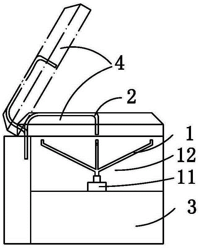
[0039] like figure 1 As shown, the OLED panel thinning device in this embodiment includes a rotating frame 1, a fluid conduit 2 and a rotating frame cavity 3, the rotating frame 1 is fixedly installed in the rotating frame cavity 3, and the port of the fluid conduit 2 is located at the rotating Right above the center of frame 1, when thinning, fix the OLED panel on the rotating frame 1. In order to facilitate the placement of the OLED panel, adjust the levelness of the OLED panel and ensure that the center of the OLED panel coincides with the center of the rotating frame 1, the rotating frame 1 in...


PUM


Abstract

The invention discloses an organic light emitting diode (OLED) panel thinning device, system and method. The OLED panel thinning device mainly comprises a rotary machine frame, a fluid guide tube and a rotary machine frame cavity, wherein the rotary machine frame is fixedly installed in the rotary machine frame cavity, and a port of the fluid guide tube is located right above the central position of the rotary machine frame. A principle is that etching liquid evenly diffuses from the center of an OLED panel to the outside by utilizing centrifugal force produced by the rotary machine frame in rotation, and then etching and thinning of the OLED panel are achieved. The invention further discloses the OLED panel thinning method based on the OLED panel thinning device. The OLED panel thinning device and method overcomes the shortcoming that the etching liquid for immersion-type thinning is polluted and accordingly the thinning quality is reduced, and meanwhile overcomes the problem that concave spots are easily formed and the etching thickness is uneven and the like in the spraying-type thinning.

Description

technical field [0001] The invention belongs to the field of OLED display technology, and in particular relates to an OLED panel thinning device, a thinning system and a thinning method. Background technique [0002] The continuous development of flat panel display technology requires OLED displays to be lighter and thinner. Limited by the manufacturing process, the thickness of the OLED substrate glass can no longer be made thinner. Therefore, the current thinning technology generally involves etching and thinning after the OLED panel is packaged. Commonly used etching thinning technologies are mainly divided into immersion thinning and spray thinning. Immersion thinning refers to the method of soaking multiple encapsulated OLED panels in etching solution for a certain period of time to achieve thinning. , its disadvantage is that the etchant of the OLED panel is likely to cause contamination of the etching solution, and the contaminated etching solution will reduce the th...

Claims


Application Information

Patent Timeline
Patent Type & Authority Patents(China)
IPC IPC(8): H01L27/32H01L21/67
Inventor 向欣任海黄俊敬启毓唐元刚何江
Owner SICHUAN CCO DISPLAY TECH
Why Eureka
Try Eureka