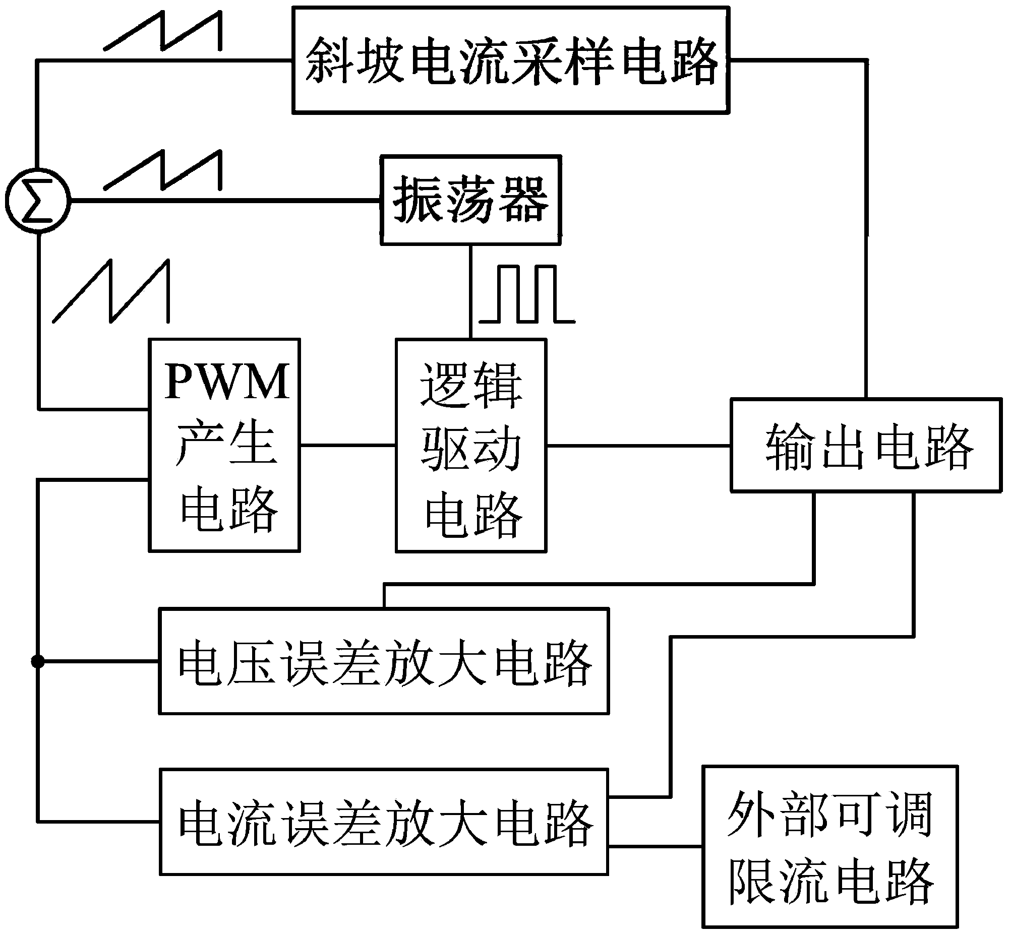
Constant-current/constant-voltage DC-DC conversion system with external adjustable current-limiting function
A DC-DC and conversion system technology, applied in the direction of output power conversion device, control/regulation system, DC power input conversion to DC power output, etc., can solve the problem of limiting the application of constant current/constant voltage DC-DC conversion system Development, non-adjustable current limit value, high design cost, etc., to achieve the effect of protecting normal operation, avoiding large current, and saving chip area
- Summary
- Abstract
- Description
- Claims
- Application Information
AI Technical Summary
Problems solved by technology
Method used
Image
Examples
Embodiment 1
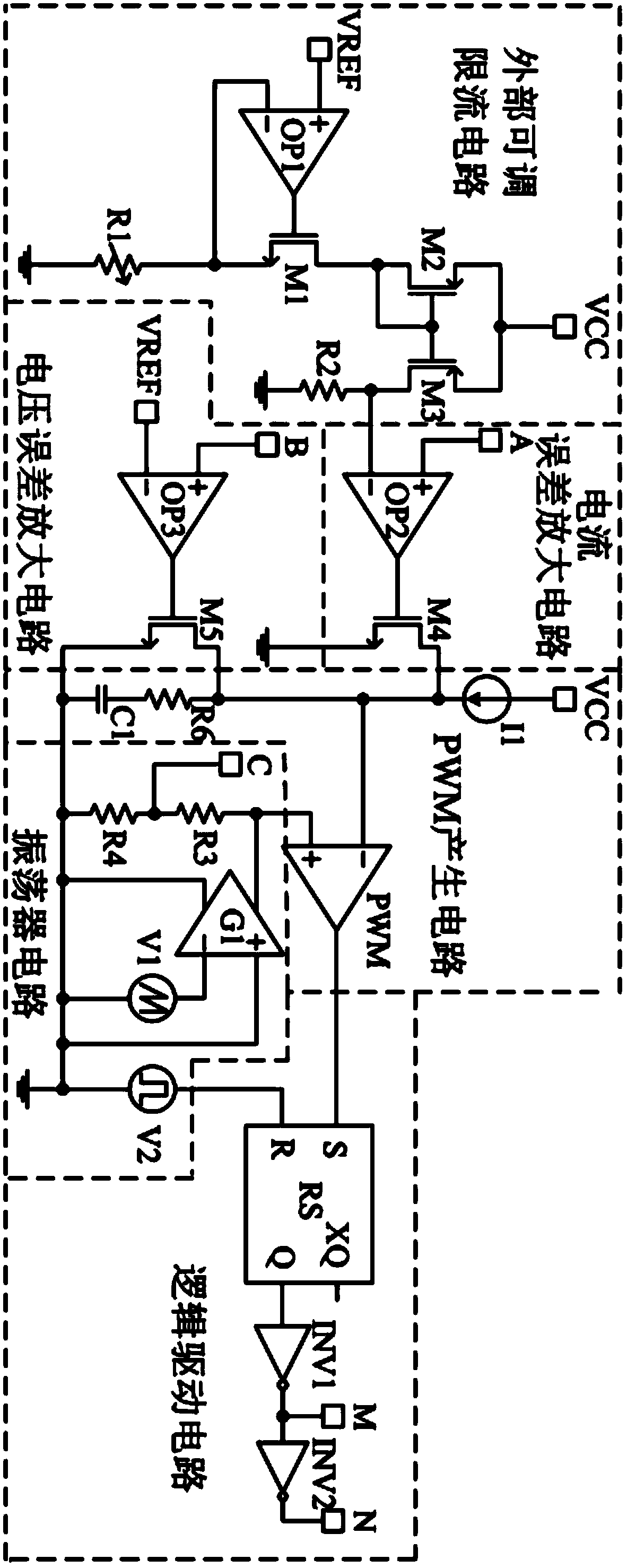
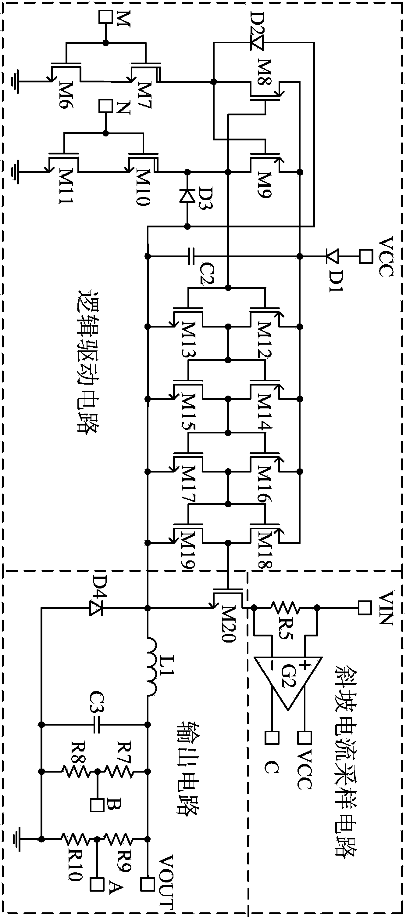
[0063] The current limiting value IF and voltage limiting value VF of the system are set to 1A and 3.3V respectively, and the selected reference voltage VREF is 0.8V. Because the sampling resistance is very small, it can be seen from formula (7) that the critical value of the load resistance is 3.3Ω. When the load resistance R93.3Ω, the system works in constant voltage mode.
[0064] For the setting of the current limit value 1A: Since when OP1 is stable, the voltage at the R1 terminal is 0.8V, if the value of R1 is adjusted to 80KΩ, the current flowing through R1 is 10μA, when the value of n is 1, that is, M2 When it is an equal-proportion mirror image with M3, the current flowing through R2 is also 10μA. If the resistance value of R2 is set to 2.5KΩ, it can be obtained from formula (2), the value of VA is 25mV, and the selected current sampling resistor R10 is 25mΩ, then the setting of the output current limit value of 1A can be realized by formula (1). If you want to chan...
Embodiment 2
[0068] The current limiting value IF and voltage limiting value VF of the system are set to 1A and 3.3V respectively, and the selected reference voltage VREF is 0.8V. Because the sampling resistance is very small, it can be seen from formula (7) that the critical value of the load resistance is 3.3Ω. When the load resistance R93.3Ω, the system works in constant voltage mode.
[0069] For the setting of the current limit value 1A: Since when OP1 is stable, the voltage at the R1 terminal is 0.8V, if the value of R1 is adjusted to 80KΩ, the current flowing through R1 is 10μA, when the value of n is 1, that is, M2 When it is an equal-proportion mirror image with M3, the current flowing through R2 is also 10μA. If the resistance value of R2 is set to 2.5KΩ, it can be obtained from formula (2), the value of VA is 25mV, and the selected current sampling resistor R10 is 25mΩ, then the setting of the output current limit value of 1A can be realized by formula (1). If you want to chan...
Embodiment 3
[0073] The current limiting value IF and voltage limiting value VF of the system are set to 1A and 3.3V respectively, and the selected reference voltage VREF is 0.8V. Because the sampling resistance is very small, it can be seen from formula (7) that the critical value of the load resistance is 3.3Ω. When the load resistance R93.3Ω, the system works in constant voltage mode.
[0074] For the setting of the current limit value 1A: Since when OP1 is stable, the voltage at the R1 terminal is 0.8V, if the value of R1 is adjusted to 80KΩ, the current flowing through R1 is 10μA, when the value of n is 1, that is, M2 When it is an equal-proportion mirror image with M3, the current flowing through R2 is also 10μA. If the resistance value of R2 is set to 2.5KΩ, it can be obtained from formula (2), the value of VA is 25mV, and the selected current sampling resistor R10 is 25mΩ, then the setting of the output current limit value of 1A can be realized by formula (1). If you want to chan...
PUM
 Abstract
Description
Claims
Application Information
 - R&D
- Intellectual Property
- Life Sciences
- Materials
- Tech Scout
- Unparalleled Data Quality
- Higher Quality Content
- 60% Fewer Hallucinations
Browse by: Latest US Patents, China's latest patents, Technical Efficacy Thesaurus, Application Domain, Technology Topic, Popular Technical Reports.
© 2025 PatSnap. All rights reserved.Legal|Privacy policy|Modern Slavery Act Transparency Statement|Sitemap|About US| Contact US: help@patsnap.com


