Spr sensor cell, and SPR sensor
A sensor element and sensor technology, applied in optical components, instruments, scientific instruments, etc., can solve the problems of fixing the analysis sample to the optical fiber and difficulty in forming a metal film, etc., and achieve the effect of excellent detection sensitivity
- Summary
- Abstract
- Description
- Claims
- Application Information
AI Technical Summary
Problems solved by technology
Method used
Image
Examples
Embodiment 1
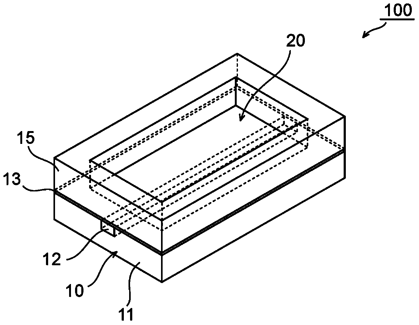
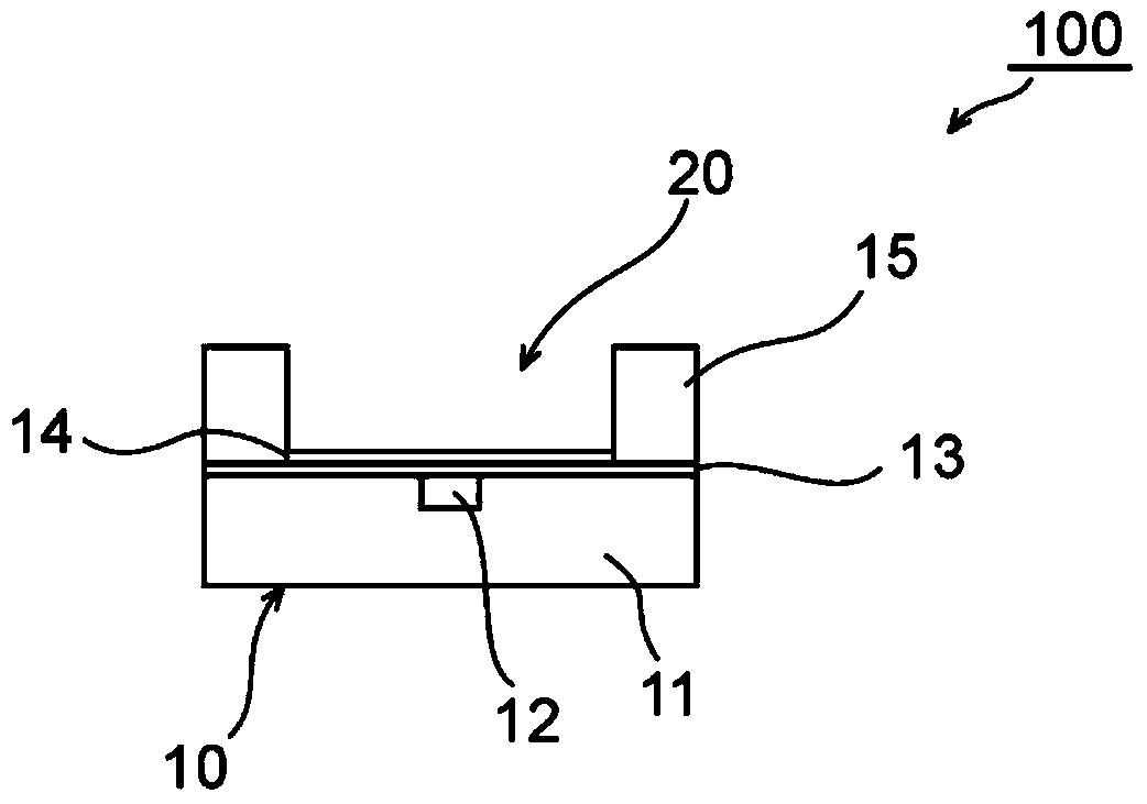
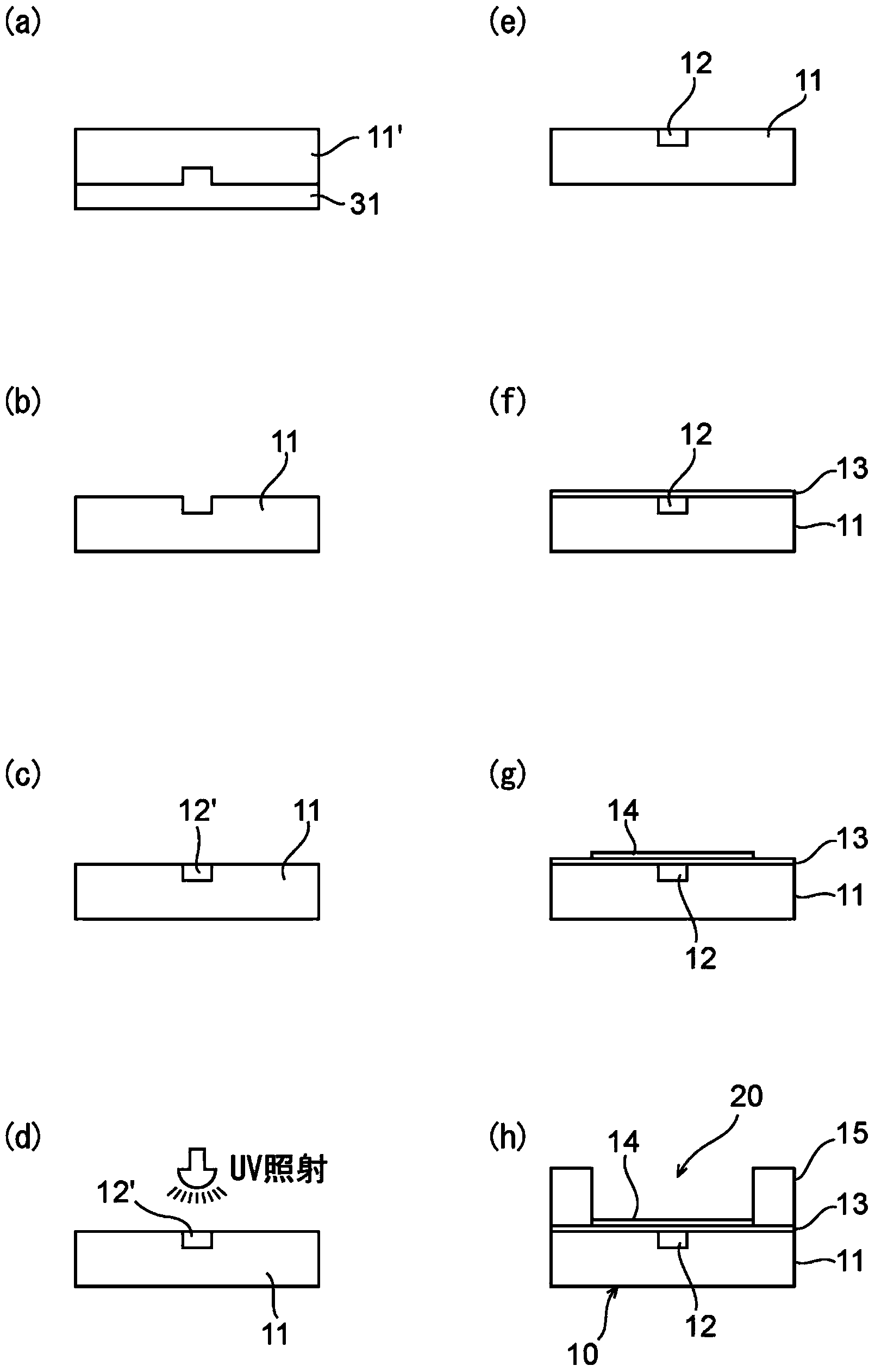
[0065] like image 3 of (a) to image 3 (e), the optical waveguide is formed by using a stamping system. Specifically, a fluorine-based UV-curable resin (“OP38Z” (trade name) produced by DIC Corporation) as a material for forming the under cladding layer was applied to a mold having protrusions corresponding to the core layer forming portions of the under cladding layer , and the resin is cured with ultraviolet rays to form an undercladding layer. The refractive index of the thus obtained lower cladding layer was 1.372. The lower cladding layer had a length of 80 mm, a width of 80 mm, and a thickness of 150 μm, and a groove portion for forming a core layer having a width of 50 μm and a thickness (depth) of 50 μm was formed in the lower cladding layer. After the lower cladding layer is peeled off from the mold, the groove portion is filled with the core layer forming material to form the core layer. By stirring and dissolving 60 parts by weight of a fluorine-based UV curabl...
Embodiment 2
[0069] Except for forming a core layer having a refractive index of 1.399 and a refractive index of 2.90×10 by using a fluorine-based UV-curable resin (“OP40Z” (trade name) produced by DIC Corporation) as a material for forming the core layer -2 (mm -1 ), the SPR sensor element and the SPR sensor were fabricated in the same manner as in Example 1, except for the core layer of the absorption coefficient. The SPR sensor thus obtained was evaluated in the same manner as in Example 1. Table 1 shows the results.
Embodiment 3
[0071] Except that by using 70 parts by weight of UV-curable resin (“FNR-061” produced by Nagase ChemteX Corporation), 30 parts by weight of UV-curable resin (“FNR-062” produced by Nagase ChemteX Corporation) and 1 part by weight of light An acid agent ("CPI-200K" produced by San-Apro Ltd.) was stirred and dissolved to prepare a composition as a material for forming a core layer to form a composition having a refractive index of 1.414 and a refractive index of 8.46×10 -2 (mm -1 ), the SPR sensor element and the SPR sensor were fabricated in the same manner as in Example 1, except for the core layer of the absorption coefficient. The SPR sensor thus obtained was evaluated in the same manner as in Example 1. Table 1 shows the results.
PUM
| Property | Measurement | Unit |
|---|---|---|
| absorption coefficient | aaaaa | aaaaa |
| thickness | aaaaa | aaaaa |
| thickness | aaaaa | aaaaa |
Abstract
Description
Claims
Application Information
 - R&D
- Intellectual Property
- Life Sciences
- Materials
- Tech Scout
- Unparalleled Data Quality
- Higher Quality Content
- 60% Fewer Hallucinations
Browse by: Latest US Patents, China's latest patents, Technical Efficacy Thesaurus, Application Domain, Technology Topic, Popular Technical Reports.
© 2025 PatSnap. All rights reserved.Legal|Privacy policy|Modern Slavery Act Transparency Statement|Sitemap|About US| Contact US: help@patsnap.com


