Tool wear monitoring method

A tool wear and acoustic emission signal technology, applied in the field of tool wear detection, can solve the problems of poor applicability, achieve the effect of improving the recognition rate and simplifying the structure

Active Publication Date: 2013-12-25
沈阳百祥机械加工有限公司
View PDF4 Cites 39 Cited by
  • Summary
  • Abstract
  • Description
  • Claims
  • Application Information

AI Technical Summary

Problems solved by technology

There is a good correspondence between the wear state of the tool and the change of the cutting force, but the change of the cutting processing condition will also cause the change of the cutting force. It is difficult to distin

Method used


Image

  • Tool wear monitoring method
  • Tool wear monitoring method

Examples


Embodiment

[0046] The superalloy GH4169 was turned with YBC carbide inserts on a CA6140 ordinary lathe.

[0047] A current sensor with the model number HZIB-C11-100P2O5 is used to monitor the state of the cutting tool. The acquisition device is a PCI-1712 data acquisition card produced by Advantech, and the sampling frequency is 1M Hz. Choose 8 different cutting parameters, collect the acoustic emission signals and current signals of 3 different wear states, and get 40 sets of signals in total. For the acoustic emission signal, extract the amplitude root mean square and the maximum power in the frequency domain, and the 8 frequency band energies of the three-layer decomposition of the db8 wavelet packet as eigenvalues; the eight frequency band energies of the three-layer decomposition of the db8 wavelet packet for the current signal are used as The eigenvalues, together with the cutting speed, depth of cut and feed rate, constitute a 21-dimensional vector, which serves as an eigenvector...


PUM


Abstract

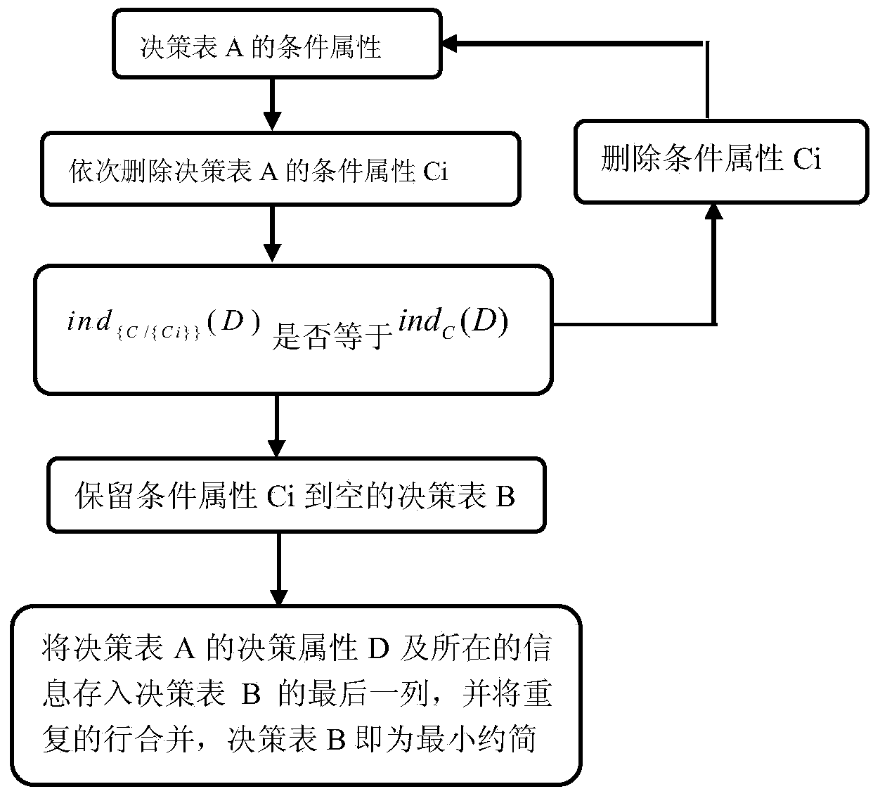
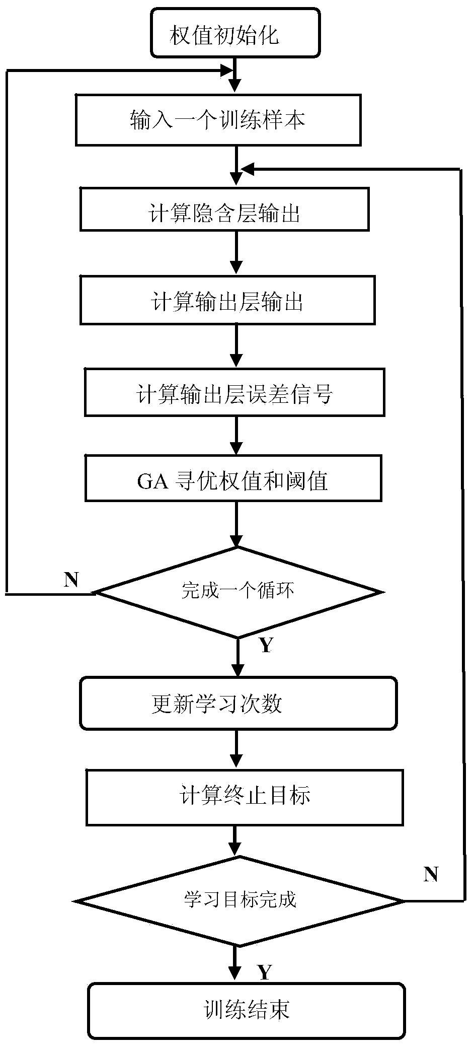
The invention relates to a real-time online tool wear monitoring method which comprises the steps of: firstly, under different cutting parameters, respectively acquiring acoustic emission signals in different wear states, current signals of a spindle motor and a feed motor in a machine tool, cutting speed, cutting depth and feed rate; taking the acquired values as condition attributes, and establishing a decision table; carrying out discretization treatment on the continuous attribute values in the decision table by adopting a self-organizing map neural network; reducing the number of the attributes by adopting the Johnson algorithm; optimizing the initial weight value and the threshold values of a back propagation (BP) neural network by the genetic algorithm, and using the reduced attribute value which is taken as an input neuron of the BP neural network to train and learn the optimized BP neural network; using the trained BP neural network to predict the tool wear degree. The method not only simplifies the structure of the neural network so as to enable the neural network to have rapid neural astringency and stronger learning ability, but also improves the recognition rate of tool wear detection.

Description

technical field [0001] The invention relates to the field of tool wear detection, in particular to a real-time online tool wear monitoring method for tool wear in precision machining of difficult-to-machine components in the aviation field. Background technique [0002] With the improvement of the automation and intelligence level of the processing system, in order to avoid damage to the machine tool, tool and workpiece, and improve the quality and dimensional accuracy of the processed workpiece, the traditional single-factor sensor has been difficult to meet the requirements of the high-precision tool state detection system. The research on tool state detection system based on multi-sensor fusion has received widespread attention. The use of multi-sensor technology can overcome the limitation that a single sensor can only provide partial information technology conditions, and obtain comprehensive status information, thereby more comprehensively reflecting the status changes...

Claims


Application Information

Patent Timeline
IPC IPC(8): B23Q17/09G06N3/08G06N3/12
Inventor 聂鹏李正强徐涛陈彦海郭勇何超
Owner 沈阳百祥机械加工有限公司
Why Eureka
Try Eureka