In situ purification system for city channel water body
A technology for purification systems and river channels, applied in chemical instruments and methods, multi-stage water/sewage treatment, water/sludge/sewage treatment, etc. , high cost problems, to achieve the effect of improving nitrogen removal capacity, improving water quality, and reducing COD load
- Summary
- Abstract
- Description
- Claims
- Application Information
AI Technical Summary
Problems solved by technology
Method used
Image

Examples
Embodiment 1
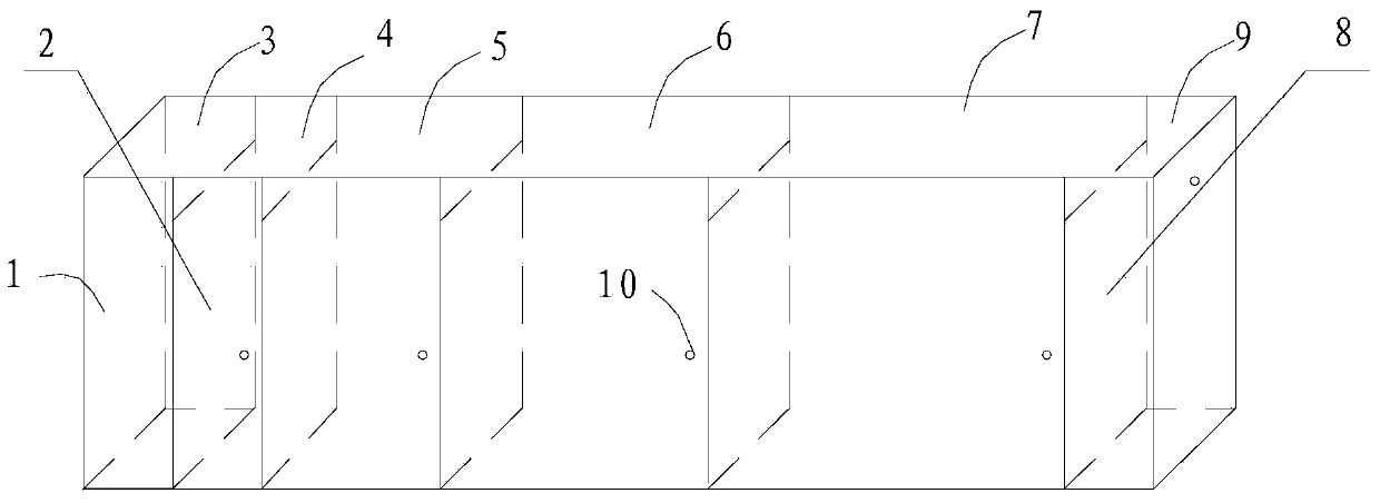
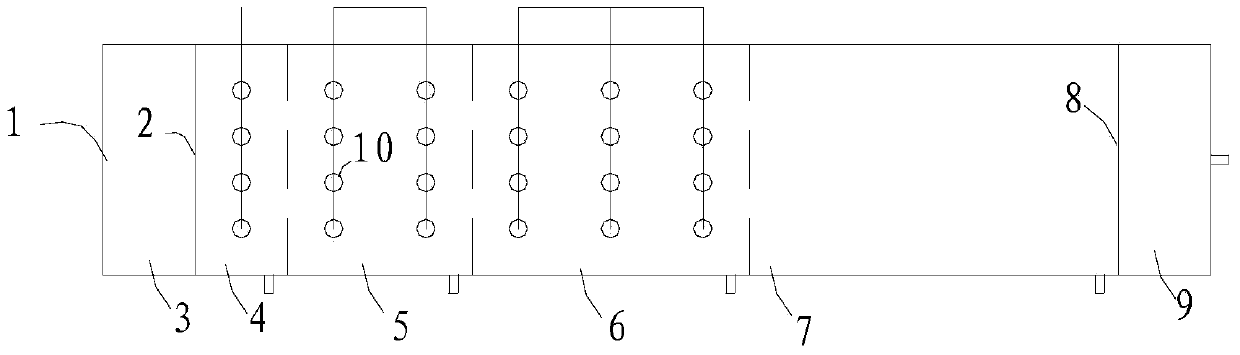
[0034] This example is in figure 1 and figure 2 The simulated urban river reactor shown was carried out, simulation A 2 / O process, simulated urban river reactor including reactor 1, the reaction, 1 effective volume 75L, with water inlet area 3, reaction area, water outlet area 9, with a first partition between the water inlet area 3 and the reaction area The water baffle 2, the second water-repelling baffle 8 is arranged between the reaction zone and the water outlet zone 3, and each section is connected. In order to simulate the light characteristics of natural rivers, reactor 1 was treated with opaque treatment around it and operated at room temperature.
[0035] The reaction zone of the reactor 1 is mainly divided into a biofilm reaction section and a floating island section, the biofilm reaction section is arranged with elastic biological filler, and the floating island section is planted with plant floating islands. The reaction area is divided into 4 sections, namely ...
Embodiment 2
[0044] This embodiment is carried out in the simulated urban river reactor, compared with embodiment 1, the simulated urban river reactor of this embodiment lacks an anoxic treatment unit 5, and others are the same as embodiment 1, simulating the A / O process, the reaction The effective volume of the device is 75L, and it is equipped with a water inlet area, a reaction area, and a water outlet area, and each section is connected. In order to simulate the light characteristics of natural rivers, the surroundings of the reactor are opaque and operated at room temperature.
[0045] The reaction zone of the reactor is mainly divided into a biofilm reaction section and a floating island section. Elastic biological fillers are arranged in the biofilm reaction section, and plant floating islands are planted in the floating island section. The reaction zone is divided into 3 sections, namely A, B, and C sections. Each section is equipped with a separate isolation aeration screen head,...
PUM
 Abstract
Description
Claims
Application Information
 - Generate Ideas
- Intellectual Property
- Life Sciences
- Materials
- Tech Scout
- Unparalleled Data Quality
- Higher Quality Content
- 60% Fewer Hallucinations
Browse by: Latest US Patents, China's latest patents, Technical Efficacy Thesaurus, Application Domain, Technology Topic, Popular Technical Reports.
© 2025 PatSnap. All rights reserved.Legal|Privacy policy|Modern Slavery Act Transparency Statement|Sitemap|About US| Contact US: help@patsnap.com