Angular vibration table

An angular vibrating table and moving coil technology, applied in the direction of instruments, etc., can solve the problems of large distortion of angular acceleration waveform, large inertia of rotating parts, narrow operating frequency range, etc. small effect

Active Publication Date: 2013-12-25
ZHEJIANG UNIV
View PDF7 Cites 12 Cited by
  • Summary
  • Abstract
  • Description
  • Claims
  • Application Information

AI Technical Summary

Problems solved by technology

The disadvantages of this kind of angular vibration table are: 1) the winding of the moving coil is difficult, the wiring is uneven, and the process is complicated; 2) the inertia of the rotating parts is large, the operating frequency range is narrow, and the distortion of the angular acceleration waveform is large; 3) due to the use of rubber cylinder springs As the recovery spring of the driving part, the range of rotation angle is limited, and the angular displacement is small

Method used


Image

  • Angular vibration table
  • Angular vibration table
  • Angular vibration table

Examples


Embodiment 1

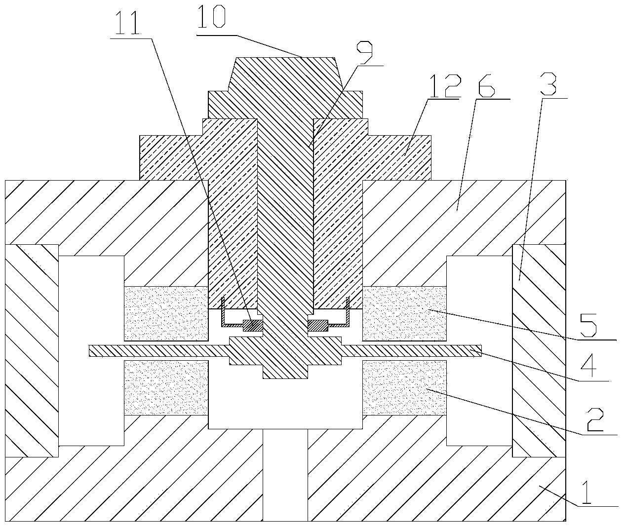
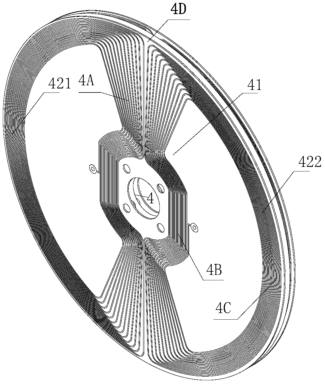
[0030] Such as figure 1 As shown, an angular vibrating table includes a base 1 made of a magnetizer, an outer wall 3 and a top cover 6, the top cover 6 is erected on the outer wall 3, and a moving assembly is installed on the top cover 6, the moving assembly includes a rotating shaft 9, The working surface 10 and the moving coil 4 fixed to the rotating shaft 9 are placed on the working surface 10 by the calibration sensor, the bearing 12 is arranged between the rotating shaft 9 and the top cover 6, the upper magnetic steel 5 is fixed on the bottom of the top cover 6, and the top of the base 1 The lower magnet 2 is fixed, the moving coil 4 is connected to the alternating current source, the moving coil 4 is a disc structure, the moving coil 4 is located between the upper magnet 5 and the lower magnet 2, and the moving coil 4 is connected to the upper magnet respectively. 5 and the lower magnetic steel 2 clearance fit.

[0031] A torsion spring 11 is fixed on the rotating shaft...

Embodiment 2

[0042] The difference between this embodiment and Embodiment 1 is that the specific structure of the bearing is refined, and the rest of the structures are the same as Embodiment 1.

[0043] Such as Figure 5 As shown, the bearing between the rotating shaft 9 and the top cover 6 is an air bearing. The air bearing includes a bearing seat 7 and an air bearing body 8. The air bearing body 8 is socketed in the bearing seat 7, and the bearing seat 7 is socketed in the top cover 6. Above, the two ends of the torsion spring 11 are fixed on the bearing seat 7 respectively.

[0044] Such as Figure 6 , 7 As shown, the bearing seat 7 is provided with an air inlet 76 connected to the air source, and the air bearing body 8 includes a journal sleeve part 8A supporting the rotating shaft 9 and a thrust part 8B supporting the worktable 10, and the journal sleeve part 8A is provided with a journal bearing restrictor 83 that introduces gas into the gap between the sleeve and the rotating sh...


PUM


Abstract

An angular vibration table comprises a base made of magnetizers, an outer wall and a top cover, wherein the top cover is erected onto the outer wall, and a movement assembly is arranged on the top cover. The movement assembly comprises a rotating shaft, a working table top and a moving coil, wherein the rotating shaft penetrates through the top cover, the working table top is fixed to the top portion of the rotating shaft, the moving coil is fixed to the bottom of the rotating shaft, the moving coil is connected with an alternating-power current source, a bearing is arranged between the rotating shaft and the top cover, a torsional spring is fixed to the rotating shaft, and the two tail ends of the torsional spring are fixed to the bearing. An upper portion magnetic steel piece is fixed to the bottom of the top cover, a lower portion magnetic steel piece is fixed to the top of the base, and the moving coil is of a disc type structure and located between and in clearance fit with the upper portion magnetic steel piece and the lower portion magnetic steel piece. The angular vibration table has the advantages of being even in moving coil arrangement, small in inertia of rotating parts, wide in operating frequency range, large in angular displacement and low in distortion degree.

Description

technical field [0001] The invention relates to an angle vibration table, in particular to an angle vibration table used for calibrating or calibrating the dynamic performance of an angle vibration sensor. Background technique [0002] With the development of modern science and technology and the improvement of automation, the application range of angular vibration sensors is becoming wider and wider. The application fields involve various sectors of the national economy and people's daily life, such as: aerospace, deep sea exploration, resource exploration, Medical equipment, automotive industry and household appliances, etc. The angular vibration sensor needs to be calibrated before leaving the factory, and it needs to be calibrated after a certain period of use or repair. As one of the key equipment for the calibration or calibration of the dynamic performance of the angular vibration sensor, the angular vibration table has attracted more and more attention. The internat...

Claims


Application Information

Patent Timeline
Patent Type & Authority Applications(China)
IPC IPC(8): G01D18/00
Inventor 何闻唐波贾叔仕周杰
Owner ZHEJIANG UNIV
Why Eureka
Try Eureka