Plasma treatment method

A plasma and reactive gas technology, applied in the field of plasma treatment, can solve problems such as poor results and poor plasma stability, and achieve the effects of improving stability, ensuring continuous ignition, and improving quality

Active Publication Date: 2013-12-25
ADVANCED MICRO FAB EQUIP INC CHINA
View PDF4 Cites 8 Cited by
  • Summary
  • Abstract
  • Description
  • Claims
  • Application Information

AI Technical Summary

Problems solved by technology

[0005] However, in the existing plasma treatment process, the stability of the plasma is poor, and it is easy to cause poor plasma treatment results.

Method used


Image

  • Plasma treatment method
  • Plasma treatment method
  • Plasma treatment method

Examples


Embodiment Construction

[0028] As mentioned in the background, in the existing plasma treatment process, the stability of the plasma is relatively poor, which easily leads to poor results of the plasma treatment.

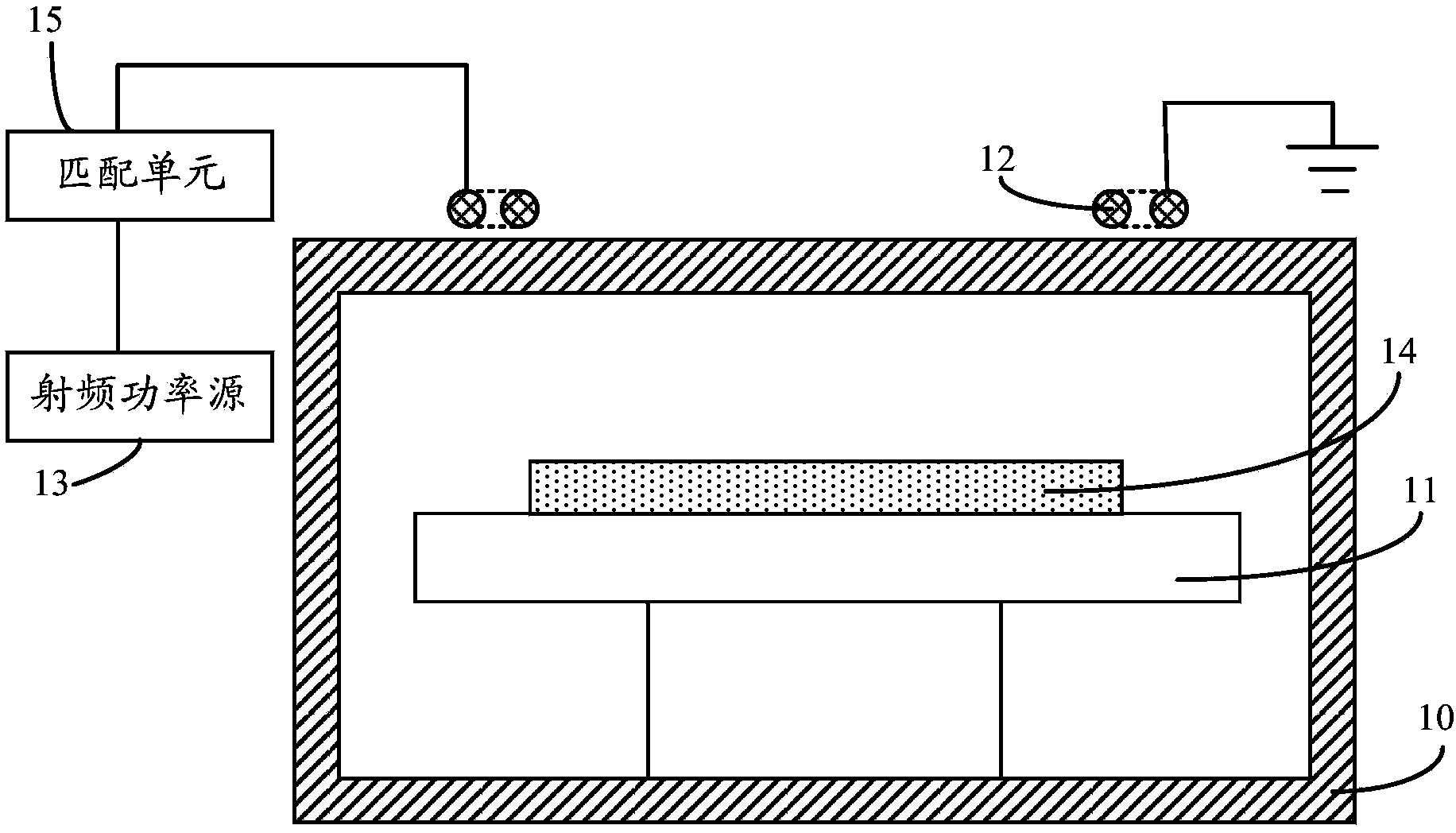
[0029] Please continue to refer figure 1 , in the existing plasma processing device, the power supply 13 provides radio frequency power to the inductively coupled coil 12 arranged on the top of the reaction chamber 10 through the matching unit 15, and the inductively coupled coil 12 causes the plasma to be generated in the reaction chamber 10, so The plasma in the reaction chamber 10 is the load of the power supply 13 . With the progress of the plasma treatment process, it is often necessary to perform multiple continuous process steps. For two adjacent process steps, the frequency of the pulse signal output by the power supply 13 needs to change, and the gas composition in the reaction chamber 10, The gas pressure will also change with the change of the process, thus causing the impedanc...


PUM


Abstract

A plasma treatment method comprises the steps of performing first plasma treatment to a substrate to be treated, leading first reaction gas into a reaction cavity and enabling a first radio-frequency power source to output radio-frequency power to the reaction cavity, wherein the output frequency of the first radio-frequency power source is the first frequency; performing second plasma treatment to the substrate to be treated, leading second reaction gas into the reaction cavity, enabling the first radio-frequency power source to output radio-frequency power to the reaction cavity, automatically adjusting the output frequency of the first radio-frequency power source to obtain the second frequency and enabling the first radio-frequency power source to be in impedance match with the reaction cavity. A transition step is further included between the first plasma treatment step and the second plasma treatment step, the gas in the reaction cavity is converted into second reaction gas from first reaction gas, and the radio-frequency power output by the first radio-frequency power source has the preset frequency ranging from the first frequency to the second frequency so that the plasma ignition can be kept. The plasma treatment method can keep plasmas stable, and the treatment quality is improved.

Description

technical field [0001] The invention relates to the technical field of semiconductor manufacturing, in particular to a plasma treatment method. Background technique [0002] Plasma treatment processes used in the manufacture of integrated circuits include plasma deposition processes, plasma etching processes, and the like. The principle of the plasma treatment process includes: using a radio frequency power source to drive a plasma generating device (such as an inductively coupled coil) to generate a strong high frequency alternating magnetic field, so that a low pressure reaction gas is ionized to generate plasma. Plasma contains a large number of active particles such as electrons, ions, excited atoms, molecules and free radicals, which can undergo various physical and chemical reactions with the surface of the wafer to be processed, making the morphology of the wafer surface changes occur, ie the plasma treatment process is complete. In addition, the active ions have hi...

Claims


Application Information

Patent Timeline
Patent Type & Authority Applications(China)
IPC IPC(8): H01L21/00H01L21/3065H01J37/32
Inventor 叶如彬浦远
Owner ADVANCED MICRO FAB EQUIP INC CHINA
Why Eureka
Try Eureka