Antenna device and receiving system

An antenna device and receiver technology, which is applied in the field of satellite antennas, can solve the problems of frequency point mutual interference, high frequency point mutual interference, low antenna precision, etc., and achieve the goals of reducing influence, expanding antenna bandwidth, and improving phase stability Effect

Active Publication Date: 2013-12-25
HARXON CORP
View PDF11 Cites 37 Cited by
  • Summary
  • Abstract
  • Description
  • Claims
  • Application Information

AI Technical Summary

Problems solved by technology

[0006] However, in the above schemes, there is a phenomenon that each frequency point interferes with each other, and this causes the problem of low antenna accuracy
[0007] Therefore, how to solve the problem of low precision caused by the phenomenon of mutual interference between frequency points has become a technical problem that must be solved in the field of satellite antennas.

Method used


Image

  • Antenna device and receiving system
  • Antenna device and receiving system
  • Antenna device and receiving system

Examples


Embodiment Construction

[0041] In order to make the technical problems, technical solutions and beneficial effects to be solved by the present invention clearer and clearer, the present invention will be further described in detail below in conjunction with the accompanying drawings and embodiments. It should be understood that the specific embodiments described here are only used to explain the present invention, not to limit the present invention.

[0042] In the embodiments of the present invention, "up and down" refer to relative positions, not absolute positions; "connection" refers to direct connection, and may also refer to indirect connection.

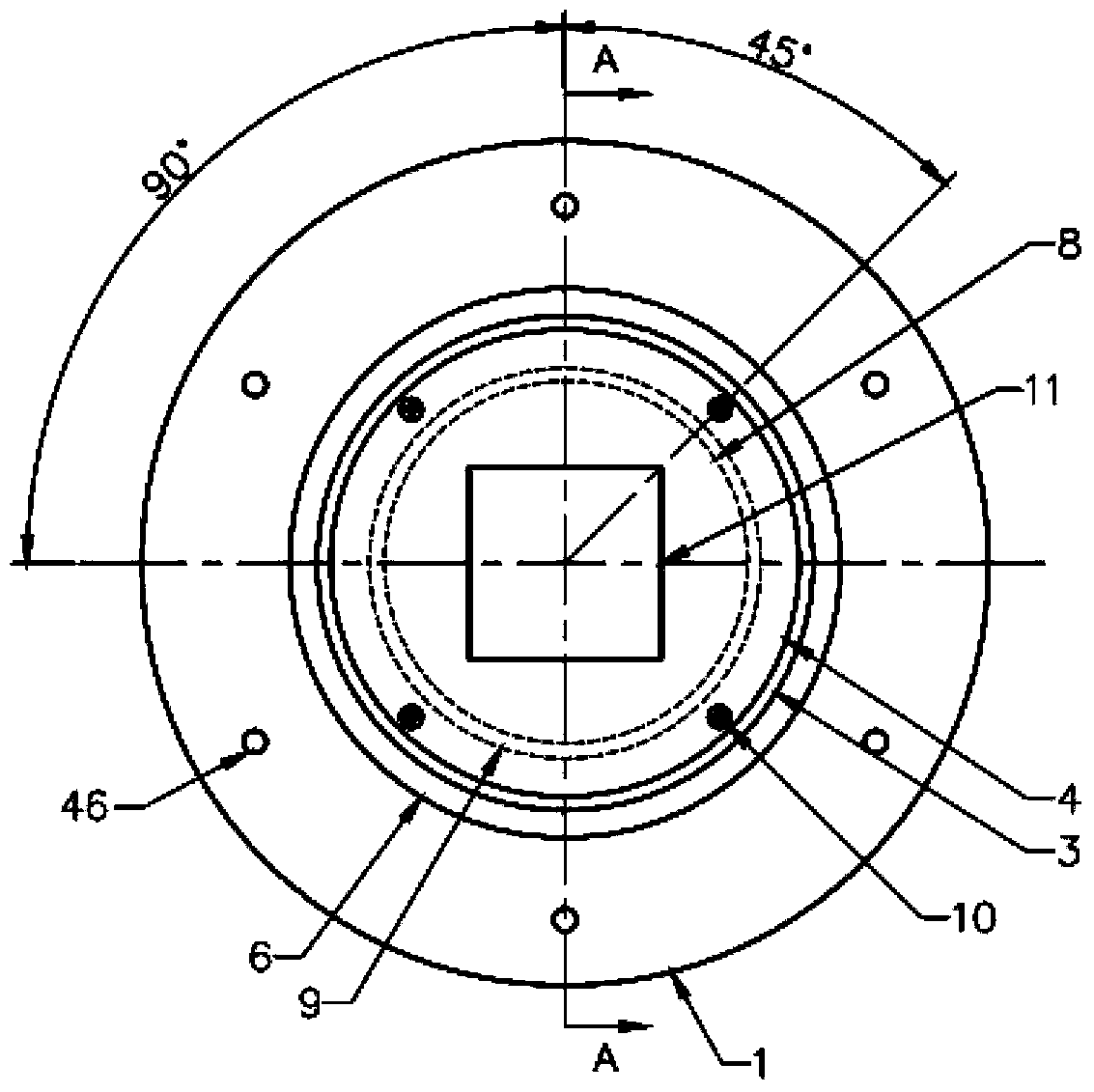
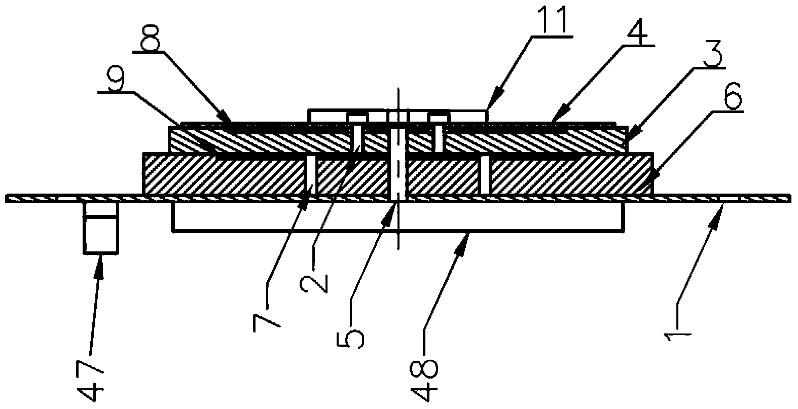
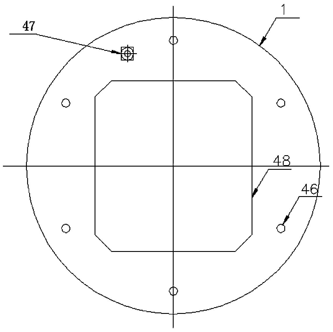
[0043] Please refer to figure 1 , figure 2 , image 3 , Figure 4 shown. The present invention provides an antenna device, which includes:

[0044]The reflector 1, the top shielding cover 11 arranged in order from top to bottom on the reflector 1, the first frequency band feed network, the substrate 4, the first frequency band radiation surface ...


PUM


Abstract

An antenna device comprises a reflecting plate, a top shielding cover arranged on one side of the reflecting plate, a first frequency band feed network, a substrate, a first frequency band radiating face, a first frequency band medium layer, a second frequency band radiating face, a second frequency band medium layer, at least one first frequency band feed probe, a second frequency band feed probe, a second frequency band feed network arranged on the other side of the reflecting plate and a low-noise amplifying circuit. The top shielding cover is fixed on the substrate, the first frequency band radiating face is connected to the first frequency band feed network through the first frequency band feed probe, the second frequency band radiating face is larger than the first frequency band radiating face and positioned on the second frequency band medium layer, the second frequency band radiating face is connected to the second frequency band feed network through a second frequency band feed probe, and the first frequency band feed network and the second frequency band feed network are connected with the low-noise amplifying circuit. The invention further provides a receiving system. By means of the antenna device and the receiving system, mutual interference between all frequency points is avoided, the phase stability of an antenna is improved, and the measuring accuracy is improved.

Description

technical field [0001] The invention relates to the field of satellite antennas, in particular to a novel feeding antenna device and a receiving system. Background technique [0002] With the continuous development of satellite navigation and measurement technology, satellite positioning system has also been widely used. At present, many countries around the world have established their own satellite positioning systems, such as China's Beidou system BDS, the United States' GPS system, Russia's GLONASS system, and Europe's Galileo GALILEO system. [0003] As the key equipment for satellite signal reception, the antenna has gradually matured. With the continuous maturity of these satellite systems and the deepening of the civilian application process, high performance has become the object pursued by consumers. [0004] Chinese Patent Publication No. CN202503105U discloses a measurement-type GNSS receiving antenna, which can effectively improve beam bandwidth, axial ratio ba...

Claims


Application Information

Patent Timeline
Patent Type & Authority Applications(China)
IPC IPC(8): H01Q1/38H01Q1/50H01Q5/00H01Q5/10H01Q5/307
CPCH01Q21/30H01Q5/40H01Q9/0414
Inventor 王春华王海波吴文平邓文雄
Owner HARXON CORP
Why Eureka
Try Eureka