Pumping unit permanent magnet speed regulation and energy conservation device

A technology of permanent magnet speed regulation and energy-saving devices, which is applied in the direction of electromechanical devices, electromechanical transmission devices, control electromechanical transmission devices, etc., can solve the problems of harmonic pollution of power supply, speed out of control, high cost, etc. The effect of oil efficiency and easy maintenance

Inactive Publication Date: 2013-12-25
TIANJIN PERMANENT MAGNETIC ENERGY SAVING TECH +1
View PDF8 Cites 3 Cited by
  • Summary
  • Abstract
  • Description
  • Claims
  • Application Information

AI Technical Summary

Problems solved by technology

For new oil wells, after the oil production frequency of the pumping unit is determined, the speed ratio of the reducer is also determined. With the change of oil well conditions, the oil recovery efficiency will decrease. To improve the oil recovery efficiency, the oil production frequency needs to be changed, that is, to change the reducer If the variable speed ratio is implemented in the original system, the cost will be very high, and usually in order to obtain the best oil production efficiency, in one oil production stroke, different speeds should be used for the upward and downward processes, which cannot be achieved in the original system
The frequency conversion speed regulation technology can solve the problem of speed regulation and energy saving, but the outdoor operation conditions limit the popularization and use of frequency converters, and the use of frequency converters does not solve the problem of different speeds between uplink and downlink, and also cannot achieve the best efficiency of oil production. It will cause harmonic pollution to the power supply
[0003] The general permanent magnet speed regulation technology can solve the problem of speed regulation and energy saving. However, due to the possibility of speed out of control during the downlink process, the oil production process cannot be completed normally, and the problem of oil production at different speeds according to the design during the uplink and downlink processes has not been solved. , also can not achieve the best oil recovery efficiency

Method used


Image

  • Pumping unit permanent magnet speed regulation and energy conservation device
  • Pumping unit permanent magnet speed regulation and energy conservation device
  • Pumping unit permanent magnet speed regulation and energy conservation device

Examples


Embodiment 1

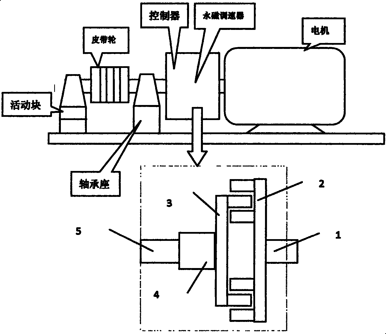
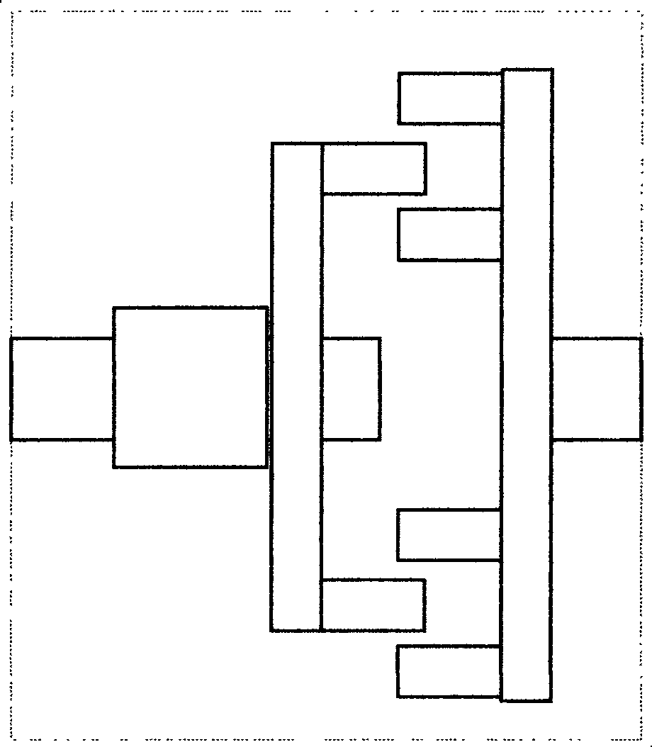
[0025] see figure 1 , 2 , 3, 4, the permanent magnet speed regulating mechanism in the pumping unit permanent magnet speed regulating energy-saving device in the present embodiment is made up of permanent magnet disk 3, conductor disk 2, brake 7, transmission shaft 5 and speed regulating mechanism 4 , The conductor disk 2 is installed on the motor shaft 1. The conductor disk 2 keeps synchronous speed with the motor, and the axial position is fixed; the speed regulating mechanism 4 makes the permanent magnet disk 3 move axially on the transmission shaft 5 under the control of the controller 6, thereby changing the permanent magnet disk 3 and The relative position of the conductor disk 2 changes the magnetic field intensity generated by the permanent magnet disk 3; when the conductor disk 2 cuts the magnetic field, the rotational speed and output torque of the permanent magnet disk 3 and the transmission shaft 5 change due to the change of the magnetic field intensity. Finally...

Embodiment 2

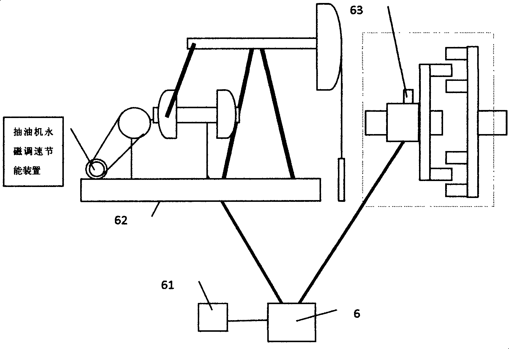
[0030] The difference between this embodiment and embodiment 1 is that, as attached Figure 6 As shown, the two bearing seats in the permanent magnet speed regulating energy-saving device of the pumping unit in this example are all installed on the right side of the pulley transmission mechanism 8, which makes the belt replacement more convenient. Simultaneously, movable block 81 also can be removed. In addition, when designing and installing two bearing housings, the ability of the pulley to withstand lateral forces should be fully considered.

[0031] In the permanent magnet speed regulating energy-saving device of the pumping unit of the present invention, if the mechanism that promotes the motion of the permanent magnet disk 3 adopts two kinds of actuators, the angle actuator and the electric push rod, the purpose of the present invention can be achieved equally; Magnet disc 3 is installed on the motor shaft 1, and conductor disc 2 is installed on the power transmission s...


PUM


Abstract

The invention relates to a pumping unit permanent magnet speed regulation and energy conservation device. The pumping unit permanent magnet speed regulation and energy conservation device is mainly composed of a permanent magnet speed regulation mechanism, a belt pulley drive mechanism and a rotating speed control system. The permanence magnet speed regulation mechanism comprises a permanent magnet plate, a conductor plate, a brake, a transmission shaft and a speed regulation mechanism, wherein the permanent magnet plate does not make contact with the conductor plate, torque is cut and delivered by magnetic lines of force through relative rotation, the speed regulation mechanism regulates the relative position of the permanent magnet plate and the conductor plate to regulate the magnetic coupling area so that speed regulation can be achieved, and the brake is used for preventing the rotating speed of the permanent magnet plate from being out of control. The belt pulley drive mechanism comprises a bearing seat, a belt pulley and a transmission shaft. The rotating speed control system comprises a controller, a displayer and a rotating speed and position detection device mechanism, wherein the controller is an intelligent device controlled by a central processor, controls the rotating speed of the belt pulley in a preset work mode according to collected parameters such as the rotating speed and the position, and sends operation parameters to the displayer. According to the pumping unit permanent magnet speed regulation and energy conservation device, the aims of saving energy and improving the oil pumping efficiency can be achieved by accurately controlling the working state of a pumping unit.

Description

technical field [0001] The invention relates to the technical field of speed regulation and energy saving for oil pumping units, in particular to a permanent magnet speed regulation and energy saving device for oil pumping units. Background technique [0002] After the motor of the pumping unit is decelerated by the reducer, the power is transmitted to the pumping unit to complete the pumping action of each stroke. For new oil wells, after the oil production frequency of the pumping unit is determined, the speed ratio of the reducer is also determined. With the change of oil well conditions, the oil recovery efficiency will decrease. To improve the oil recovery efficiency, the oil production frequency needs to be changed, that is, to change the reducer If the variable speed ratio is implemented in the original system, the cost will be very high, and usually in order to obtain the best oil recovery efficiency, in one oil production stroke, different speeds should be used for ...

Claims


Application Information

Patent Timeline
Patent Type & Authority Applications(China)
IPC IPC(8): H02K51/00H02P17/00
Inventor 周庆根邓三鹏蒋卫杰田南平王何新邢嘉珍
Owner TIANJIN PERMANENT MAGNETIC ENERGY SAVING TECH
Why Eureka
Try Eureka