

Electrostatic spinning device for preparing nanofibers
Patent Information
- Authority / Receiving Office
- CN · China
- Patent Type
- Applications(China)
- Current Assignee / Owner
- TIANJIN POLYTECHNIC UNIV
- Publication Date
- 2014-01-01
Smart Images
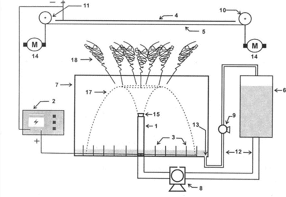
Figure 1 
Figure 2 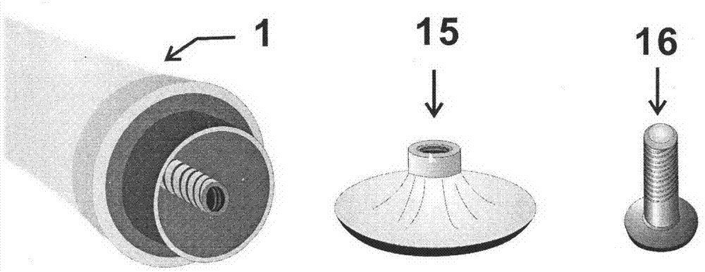
Figure 3
Abstract
Description
Technical field
[0001] The invention relates to an electrostatic spinning device capable of preparing nanofibers, which belongs to the technical field of textiles and new materials. Specifically, a liquid jet is used to spray a thin liquid film similar to a bellflower shape, and is used in a high-voltage electrostatic generator, an electrode and a receiving curtain. Under the joint action of the liquid film, multiple jets are generated at the top of the liquid film and finally form a device for nanofiber felt. Background technique
[0002] Electrospinning technology is a technology that uses electrostatic force to generate a jet of polymer solution or melt and finally solidify into nanofibers. The main principle of this technology is to first make the polymer solution or melt form curved liquid droplets, liquid column films, bubbles, crater-like bulges, etc., and then use electrostatic force to eject a jet from the top of the curved surface. The jet flies to the negative plate u...