Supercharge Your Innovation With Domain-Expert AI Agents!

Automatic pulling service system and operating method

An operation system and operation method technology, which is applied to the automatic lifting and lowering operation system and the field of operation, can solve the problems of occupying non-technical operation time of the lifting device, affecting the working independence of the lifting device, and failing to give full play to the equipment efficiency. Compact, avoid frequent commutation, small footprint effect

Inactive Publication Date: 2014-01-01
CHINA UNIV OF PETROLEUM (EAST CHINA)
View PDF5 Cites 17 Cited by
  • Summary
  • Abstract
  • Description
  • Claims
  • Application Information

AI Technical Summary

Problems solved by technology

In the design, it has been considered that the lifting method of the hook of the winch will intensify the shaking during the movement of the pipe string, which will cause difficulties in the automatic operation of the wellhead; therefore, a guide rail structure is designed to stabilize the trajectory of the traveling block
[0004] However, during the transmission of the pipe string, the external push action of the hook of the traveling block is required, which additionally takes up the non-technical operation time of the lifting device, increases the auxiliary mechanism around the hook (pipe string straightening device, etc.), and increases the space. The stroke affects the independence of the lifting device and cannot fully exert the efficiency of the equipment itself
Therefore, the efficiency of domestic automatic operation equipment is generally low, and it is difficult to popularize and apply

Method used


Image

  • Automatic pulling service system and operating method
  • Automatic pulling service system and operating method
  • Automatic pulling service system and operating method

Examples


Embodiment Construction

[0035] Below in conjunction with accompanying drawing, describe in detail by embodiment:

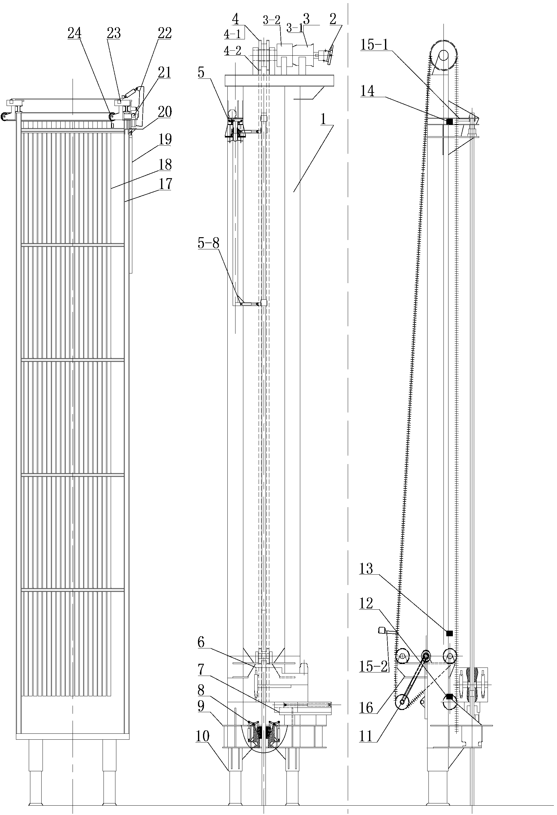
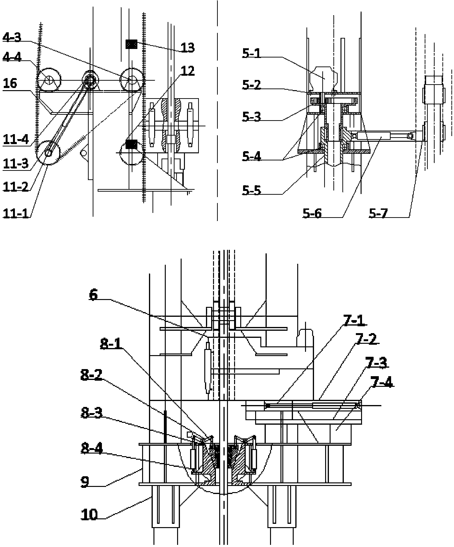
[0036] Such as figure 1 As shown, the automatic lifting operation system mainly includes an automatic lifting device and an automatic string processing device.

[0037] The automatic lifting device, which acts as a frame, mainly includes a parallel support 1, a wellhead workbench 9, a sprocket support platform 16 and a top support 5-1. The above components are mainly formed by welding; the main working mechanism is a chain circulation Lifting mechanism, including driving sprocket 4-1, transmission chain 4-2, front and rear guide wheels 4-3 and 4-4, chain give way mechanism 11, and main clamp 15 on two sets of special chain links of chain; There is a column transmission assembly 5, which is installed on the top bracket 5-2, including the hydraulic motor 5-1, the internal gear reduction device 5-3, the thrust bearing 5-4, the main rotating arm 5-5, and the main transmission arm telescopic...


PUM


Abstract

The invention discloses a novel automatic well pulling service system and an improved operating method. The automatic well pulling service system is characterized by comprising a set of chained circular pulling device, an independent tubular column conveying assembly, an automatic tube box, an automatic retractable hydraulic tong, power clamping tiles, a coupling monitoring device and the like. By the automatic well pulling service system, high-efficient automatic unmanned pulling service at the mouth of a well can be realized, and operations from lifting and shackle removing of tubular columns to conveying and discharging of the tubular columns as well as counter operations can be completed; due to a chained lifting mechanism, shaking during lifting can be avoided; two sets of main clamps are distributed evenly and can be cyclically utilized sequentially, so that idle strokes are reduced; due to a special tubular column processing function, time occupation and space interference of pipe distributing and mounting to a lifting device are reduced, and working efficiency is effectively guaranteed; due to the automatic tube box, vertical discharge can be performed on the tubular columns, occupied area is small, arrangement is convenient, and labor intensity of workers is greatly reduced. The automatic well pulling service system and the operating method can be widely applied to minor land repair work.

Description

Technical field [0001] A new type of automation system for workover and tripping operation, as well as the improved operation method, can realize high-efficiency unmanned automatic tripping and tripping operation at the wellhead, and complete the automatic operation of the pipe string from lifting, breaking out to pipe string transmission and discharge . Background technique [0002] At present, oilfield minor repairs use traditional operation methods and equipment, requiring 4 to 5 workers to work together, and almost every process requires workers to participate, especially wellhead operations that are highly random, require high flexibility and intelligence; workover Machine and hydraulic tongs only play a power-assisted role, so the labor intensity of workers is very large. [0003] A variety of automatic workover equipment developed in China basically continues the winch-traveler-hook lifting method of the traditional workover rig; it uses power elevators and telescopi...

Claims


Application Information

Patent Timeline
IPC IPC(8): E21B19/14E21B19/18E21B19/00E21B41/00
Inventor 綦耀光苑珍东陈波杜继芸吴天宠
Owner CHINA UNIV OF PETROLEUM (EAST CHINA)
Features
  • R&D
  • Intellectual Property
  • Life Sciences
  • Materials
  • Tech Scout
  • Unparalleled Data Quality
  • Higher Quality Content
  • 60% Fewer Hallucinations
Learn More