
Trimming machine for trimming base of damper

A damper and hemming machine technology, applied in the field of hemming machines, can solve the problems of slow hemming speed, low efficiency and poor accuracy of manual hemming, and achieve the effects of high speed, high efficiency and high precision

Active Publication Date: 2014-01-08
宁波安纳杰模塑科技有限公司
View PDF6 Cites 4 Cited by
  • Summary
  • Abstract
  • Description
  • Claims
  • Application Information

AI Technical Summary

Problems solved by technology

However, in the prior art, no suitable special equipment can be found to curl the edge of the upper opening of the cylinder, and the manual curling speed is slow, the precision is poor, and the efficiency is low.

Method used


Image

  • Trimming machine for trimming base of damper
  • Trimming machine for trimming base of damper
  • Trimming machine for trimming base of damper

Examples


Embodiment Construction

[0014] The present invention will be further described below in conjunction with the accompanying drawings and specific embodiments.

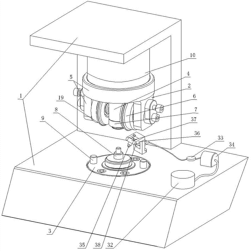
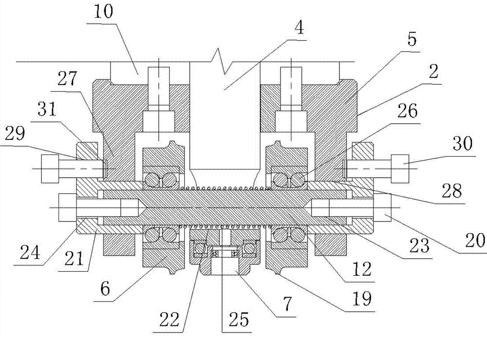
[0015] Such as figure 1 , figure 2 , image 3 , Figure 4 As shown, the present invention is used for the hemming machine of damper base hemming, and it comprises frame 1. Frame 1 is provided with elevating device 10, and the elevating part of elevating device 10 is connected with machine head 2, and machine head 2 comprises upper positioning column 4, wheel frame 5 and two rollers 6. Specifically, the lifting device 10 includes a cylinder, the cylinder body of the cylinder is fixed to the frame 1 , and the piston rod of the cylinder is fixed to the wheel frame 5 of the machine head 2 . Upper positioning post 4 and two rollers 6 are all installed on the wheel frame 5 . The two rollers 6 are separated on both sides of the upper positioning column 4, and the circumferential surface of each roller 6 is provided with a radial protruding ring ...


PUM


Abstract

The invention discloses a trimming machine for trimming a base of a damper. The trimming machine comprises a machine frame (1), a machine head (2) is arranged on the machine frame (1), a rotary disc (3) driven by an electric motor is further arranged on the machine frame (1), an upper locating column (4) and two rollers (6) are respectively arranged on the wheel carrier (5), a device for adjusting the positions of the rollers (6) is further arranged on the wheel carrier (5), a radial convex ring (19) is arranged on the circumference face of each roller (6), and a top head (7) is matched with the bottom end of the upper locating column (4) in a rotatable mode. A lower locating column (8) and a linkage pin (9) are arranged on the rotary disc (3). The trimming machine further comprises a numerical control system, a first pressure sensor is arranged on the top head (7), and the numerical control system is respectively connected with the first pressure sensor and the electric motor driving the rotary disc (3). The trimming machine is fast in speed, high in precision and high in efficiency.

Description

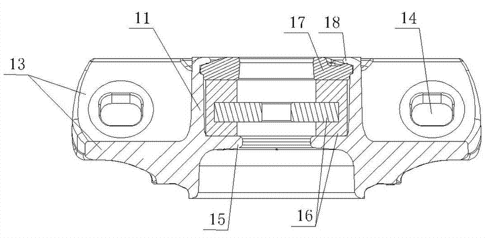
technical field [0001] The invention relates to a hemming machine, in particular to a hemming machine used for rolling out hemming, ie hemming, to a damper base. Background technique [0002] The base of the automobile damper, which includes a cylinder and a bottom plate fixed to the cylinder. There are two through holes on both sides of the cylinder on the bottom plate. A limit ring is provided at the lower opening of the cylinder. The shock absorbing ring and the cover plate, the shock absorbing ring rests on the limit ring, and the cover plate rests on the shock absorbing ring. During assembly, after the damping ring and the cover plate are loaded into the cylinder body, the edge of the upper opening of the cylinder body needs to be crimped inward, and the cover plate and the shock absorber ring are pressed onto the limit ring by crimping. However, in the prior art, no suitable special-purpose equipment can be found to curl the edge of the upper opening of the cylinder, ...

Claims


Application Information

Patent Timeline
Patent Type & Authority Applications(China)
IPC IPC(8): B21D19/06
Inventor 朱红光
Owner 宁波安纳杰模塑科技有限公司
Learn More