A compensating integrated motor electronic control braking system

A technology that integrates motors and electronically controlled brakes. It is applied in the direction of brakes, brake transmissions, and vehicle components. It can solve problems such as slow system response, difficult matching technology, and vacuum degree dependence, so as to ensure safe and reliable operation. The matching design is flexible and convenient, and the effect of reducing the braking distance

Active Publication Date: 2016-05-18
JILIN UNIV
View PDF9 Cites 2 Cited by
  • Summary
  • Abstract
  • Description
  • Claims
  • Application Information

AI Technical Summary

Problems solved by technology

However, there are also some problems in this system: the mechanical parts and hydraulic pipelines are complex, and after integrating functions such as ABS, TCS and ESP, the system structure is more complicated, the vacuum booster is bulky, and the vacuum degree depends on the change of the engine's working conditions, the size of the booster Unable to maintain stability, slow system response
Especially in the new energy vehicles widely promoted in my country in recent years, due to the lack of vacuum boosting sources, if the traditional solution is adopted, additional boosting sources such as vacuum pumps and vacuum tanks are bound to be added, the production cost is high, and the matching technology is difficult
[0003] The invention patent of "an electric power-assisted braking system" (application number is 200710111537.5, publication number is CN10132778A, publication date is 2008.12.24), the structure of the system needs to add an additional clutch matching design, the overall radial The size and axial size are both large, and the integration of active safety functions such as ABS, TCS, and ESP, which are widely used at present, is not considered. After the motor or reduction mechanism fails, the safety and reliability of the system work is also not considered.

Method used


Image

  • A compensating integrated motor electronic control braking system
  • A compensating integrated motor electronic control braking system
  • A compensating integrated motor electronic control braking system

Examples


Embodiment Construction

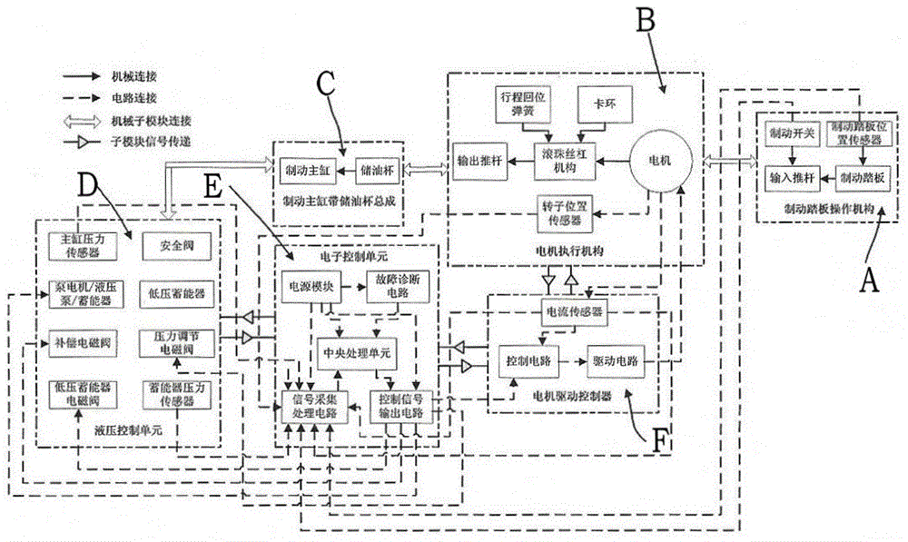
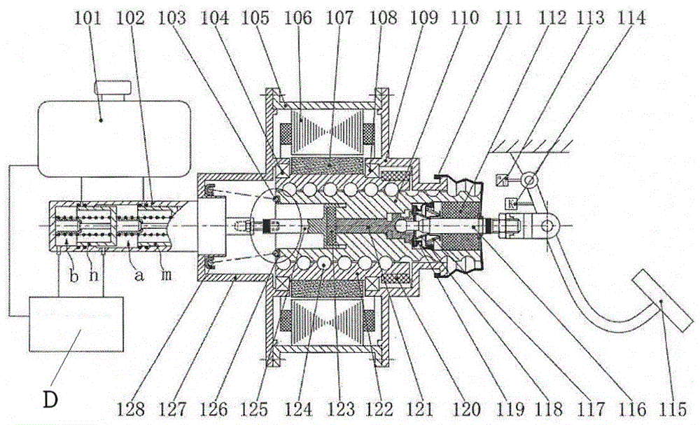
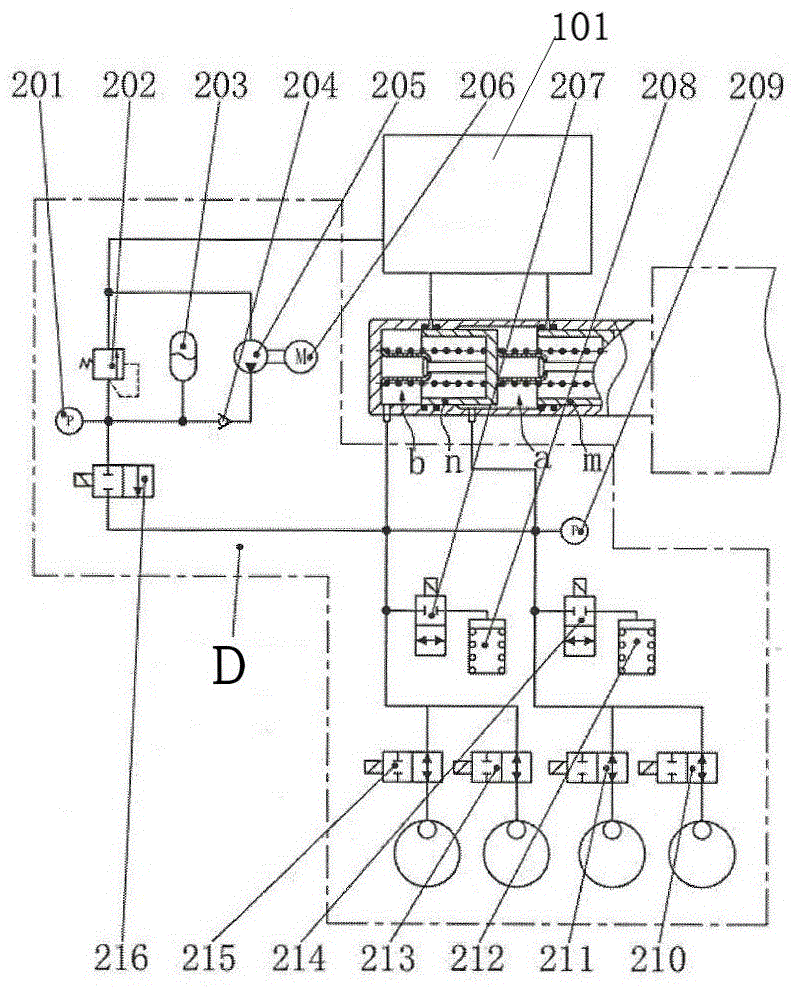
[0029] see Figure 1 to Figure 8As shown, the present invention is composed of a brake pedal operating mechanism A, a motor actuator B, a brake master cylinder with an oil storage cup assembly C, a hydraulic control unit D, an electronic control unit E and a motor drive controller F. Pedal operating mechanism A is connected to motor actuator B, motor actuator B is connected to brake master cylinder with oil storage cup assembly C, hydraulic control unit D is respectively connected to brake master cylinder with oil storage cup assembly C and each circuit The moving wheel cylinder is mechanically connected through hydraulic oil pipes and joints, the electronic control unit E is respectively connected to the hydraulic control unit D and the motor drive controller F circuit, and the motor drive controller F is connected to the motor actuator B circuit;

[0030] The brake pedal 115 of the brake pedal operating mechanism A is respectively connected to the brake switch 114, the brake...


PUM


Abstract

The invention discloses a compensation type integrated-motor electronic control brake system composed of a brake pedal operation mechanism, a motor execution mechanism, a brake master cylinder with oil storage cup assembly, a hydraulic control unit, an electronic control unit and a motor driving controller. The brake pedal operation mechanism is connected with the motor execution mechanism. The motor execution mechanism is connected with the brake master cylinder with oil storage cup assembly. The hydraulic control unit is respectively and mechanically connected with the brake master cylinder with oil storage cup assembly and each brake wheel cylinder through a hydraulic oil pipe and a connector. The electronic control unit is respectively in circuit connection with the hydraulic control unit and the motor driving controller. The motor driving controller is connected with the motor execution mechanism through a circuit. In the process of operation of an automobile, the compensation type integrated-motor electronic control brake system can rapidly and precisely recognize the braking intention of a driver, external operation conditions of the automobile, and the automobile state, according to the actual operation working conditions, active safety control such as ABS, TCS and ESP over the automobile is conducted in real time, the automobile is prevented from entering dangerous working stations such as the unstable state, and stable parking can be achieved in the situation that the system is ineffective.

Description

technical field [0001] The invention relates to an integrated motor electronic control braking system in the technical field of automobile chassis, in particular to a compensation type integrated motor electronic control braking system in the technical field of automobile chassis. Background technique [0002] The speed of modern automobiles continues to increase, and the braking performance of automobiles is directly related to the safety of people's lives and property. Good braking performance is an important guarantee for safe driving of automobiles. The hydraulic braking system widely used in modern automobiles mainly includes brake pedal, brake master cylinder, vacuum booster, hydraulic pipeline, brake and other parts. When the driver applies the brakes, he mainly relies on the vacuum booster to generate high-pressure brake fluid to achieve wheel braking. The traditional vacuum booster braking system can effectively reduce the driver's driving fatigue, and the technolo...

Claims


Application Information

Patent Timeline
Patent Type & Authority Patents(China)
IPC IPC(8): B60T13/20B60T13/66B60T13/74
Inventor 李静杨雄
Owner JILIN UNIV
Why Eureka
Try Eureka