Novel asphalt concrete pavement structure

A technology of asphalt concrete and pavement structure, which is applied to the cohesive pavement paved on site, roads, roads, etc., to achieve the effects of preventing rainwater erosion, high resistance to deformation and durability, and preventing landslides

Inactive Publication Date: 2014-01-08
聂晓鸿
View PDF0 Cites 14 Cited by
  • Summary
  • Abstract
  • Description
  • Claims
  • Application Information

AI Technical Summary

Problems solved by technology

[0002] As we all know, asphalt concrete pavement is a road paved with asphalt concrete, which is widely used in the field of road engineering because of its good shape and high construction and maintenance efficiency; the existing asphalt concrete pavement structure, usually from bottom to top It includes the base layer, the slurry seal layer combined with the penetrating oil, and the surface layer in sequence. The surface layer includes the lower layer of coarse-grained asphalt concrete, the middle layer of medium-grained asphalt concrete, and the upper layer of fine-grained asphalt concrete from bottom to top; the base layer It mainly bears the vertical force of the wheel transmitted by the surface layer, and spreads it to the cushion layer and soil foundation below. The slurry seal layer is a certain thickness of asphalt paved on the base layer to close the surface gap and prevent water intrusion. Thin layer of mixed material and penetrating layer oil are formed by spraying liquid petroleum asphalt, emulsified asphalt, etc. The effect of the vertical force of the wheel and spread it to the base; this kind of asphalt concrete pavement structure can be better used in urban road traffic, but in mountainous roads, especially mountainous roads in plateau areas, due to the changing , especially in summer, the rainfall is relatively large, which requires the road to have high quick-drying and drainage performance, and also has a certain function of preventing road collapse. However, the asphalt concrete pavement structure in the prior art is difficult to meet this requirement

Method used


Image

  • Novel asphalt concrete pavement structure

Examples


Embodiment Construction

[0009] The specific implementation manners of the present invention will be further described in detail below in conjunction with the accompanying drawings and embodiments. The following examples are used to illustrate the present invention, but are not intended to limit the scope of the present invention.

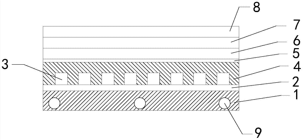
[0010] Such as figure 1 As shown, the novel asphalt concrete pavement structure of the present invention comprises a base layer 1, a mortar adhesion layer 2, a cement concrete prefabricated block 3, a crushed stone layer 4, a slurry seal layer 5, a coarse-grained asphalt concrete layer 6, and a medium-grained asphalt The concrete layer 7 and the asphalt mastic macadam mixture layer 8 are covered with a mortar adhesion layer above the base layer, and cement concrete prefabricated blocks parallel to each other and arranged at intervals are arranged above the mortar adhesion layer. The long sides of the cement concrete prefabricated blocks are The extension direction of the ...


PUM


Abstract

The invention discloses a road pavement structure, and particularly relates to a novel asphalt concrete pavement structure. The novel asphalt concrete pavement structure has high quick-drying and water drainage performance, is obvious in supporting effect and has certain collapsing preventive performance. A mortar bonding layer covers a base layer, cement concrete prefabricated blocks arranged in parallel and at intervals are arranged on the mortar bonding layer, the long edges of the cement concrete prefabricated blocks are perpendicular to the stretching direction of a road, a rubble layer is padded in clearances between adjacent cement concrete prefabricated blocks and covers the cement concrete prefabricated blocks, a slurry seal layer, a coarse grain type asphalt concrete layer, a medium grain type asphalt concrete layer and an asphalt mastic rubble mixed material layer cover the rubble layer from bottom to top in sequence, the base layer is a cement stabilizing aggregate base layer, and the rubble layer comprises rubbles and aggregate chips padded in the clearances among the rubbles.

Description

technical field [0001] The invention relates to the technical field of road engineering, in particular to a novel asphalt concrete pavement structure. Background technique [0002] As we all know, asphalt concrete pavement is a road paved with asphalt concrete, which is widely used in the field of road engineering because of its good shape and high construction and maintenance efficiency; the existing asphalt concrete pavement structure, usually from bottom to top It includes the base layer, the slurry seal layer combined with the penetrating oil, and the surface layer in sequence. The surface layer includes the lower layer of coarse-grained asphalt concrete, the middle layer of medium-grained asphalt concrete, and the upper layer of fine-grained asphalt concrete from bottom to top; the base layer It mainly bears the vertical force of the wheel transmitted by the surface layer, and spreads it to the cushion layer and soil foundation below. The slurry seal layer is a certain ...

Claims


Application Information

Patent Timeline
Patent Type & Authority Applications(China)
IPC IPC(8): E01C7/32
Inventor 聂晓鸿
Owner 聂晓鸿
Why Eureka
Try Eureka