Pneumatic double-hand rubbing bionic device

A two-handed, pneumatic technology, used in transmissions, fluid transmissions, belts/chains/gears, etc., can solve the problems of high cost, high cost, complex structure, etc., and achieve high work reliability, widespread use, and simple structure. Effect

Inactive Publication Date: 2014-01-08
SUZHOU UNIV
View PDF6 Cites 3 Cited by
  • Summary
  • Abstract
  • Description
  • Claims
  • Application Information

AI Technical Summary

Problems solved by technology

This not only makes the whole device extremely large and complex, but also extremely expensive
Such as the kneading massager disclosed in Chinese patent document CN 102940566 A, not only the structure is extremely complicated, but also fails to give the trajectory of bionic motion; another example is the numerical control rubbing type grinding machine disclosed in Chinese patent document CN 103252709 A, then adopted 3 servo The motor, as well as the extremely complex mechanical transmission system, is bulky and expensive
From a kinematic point of view, no substantial hands-rubbing bionic device has yet been retrieved

Method used


Image

  • Pneumatic double-hand rubbing bionic device
  • Pneumatic double-hand rubbing bionic device
  • Pneumatic double-hand rubbing bionic device

Examples


Embodiment 1

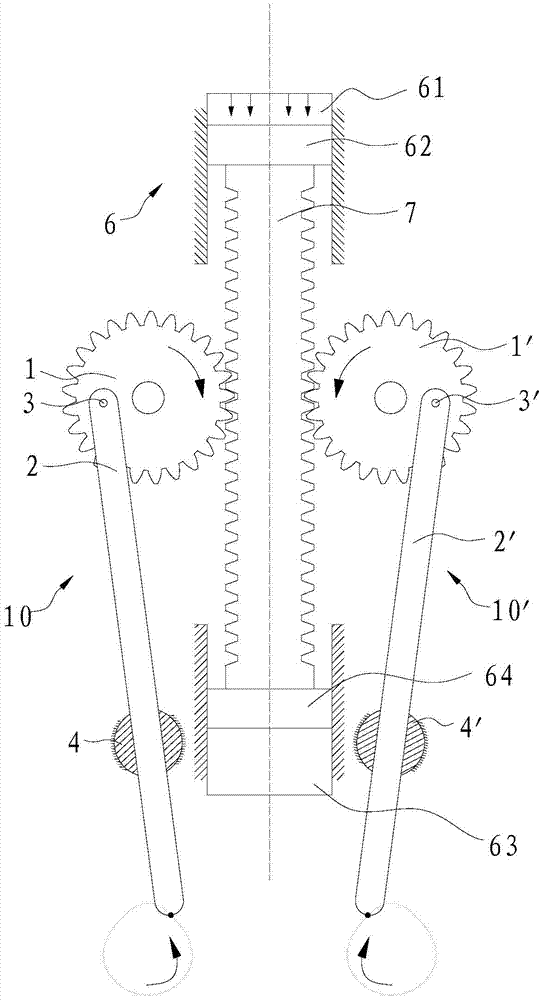
[0028] see figure 1 The shown bionic device for pneumatic hands rubbing includes a frame (not shown in the figure), and two sets of rubbing components 10, 10' arranged on the frame.

[0029] The kneading assembly 10 includes a gear 1 which is rotatably arranged on the frame around the axis, a connecting rod 2 which is rotatably arranged on the gear 1 through a pin shaft 3, and is hinged on the frame and can rotate around its own axis. Cylinder 4. There is an eccentric pin hole on the gear 1, the center line of the pin hole is parallel to the axis line of the gear 1, one end of the pin shaft 3 is connected to the upper part of the connecting rod 2, and the other end is rotatably passed through the above pin hole middle.

[0030] The axis line of the cylinder 4 is parallel to the axis line of the gear 1, and the cylinder 4 is provided with a through hole penetrating in the radial direction. The lower end is exposed outside the through hole. A plane low pair is formed b...

Embodiment 2

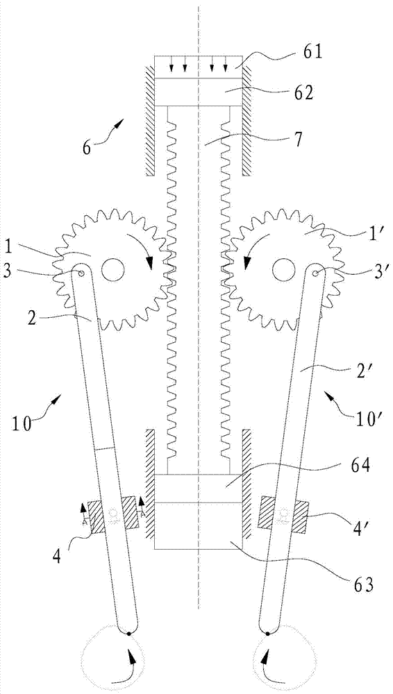
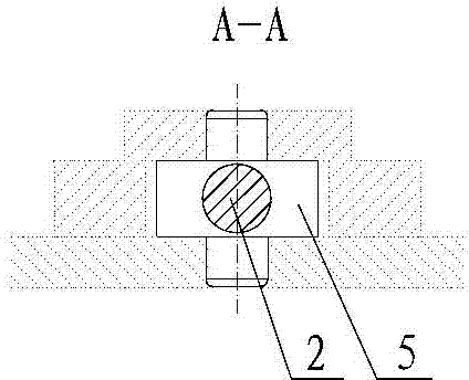
[0035] see figure 2 Shown is a bionic device for rubbing with both hands, the difference between this bionic device and Embodiment 1 is mainly in the setting of the parts that provide the guides of the connecting rods 2, 2'. In this embodiment, the connecting rod 2, 2' is provided as the center of the sliding seat 5, 5' hinged on the frame, and the two axial ends of the sliding seat 5, 5' are at the hinge point on the frame. The connecting line is parallel to the axes of the gears 1 and 1'. The sliding seats 5, 5' are respectively provided with through holes for the connecting rods 2, 2' to penetrate, and the connecting rods 2, 2' are respectively fitted in the through holes on the sliding seats 5, 5' with a clearance fit. 2, 2' and the sliding seat 5, 5' form a plane low pair, when the double-sided rack 7 moves along the length direction and drives the gear 1 and the gear 1' to rotate, the connecting rod 2, 2' is respectively on the pin shaft 3, 3 'Under the action of sl...


PUM


Abstract

The invention discloses a pneumatic double-hand rubbing bionic device. According to the pneumatic double-hand rubbing bionic device, only the simple parts including air cylinders, double-face racks, gears, connecting rods and cylinders or sliding bases are used, and the complex plane motion of simulating double-hand rubbing can be realized, wherein the centers of the cylinders or the centers of the sliding bases are hinged to a machine frame. Rubbing tools with different functions are fixed to the lower ends of the connecting rods so that various pneumatic double-hand rubbing bionic devices with different functions can be formed. The pneumatic double-hand rubbing bionic device is extremely simple in structure, especially low in manufacturing cost, high in working reliability, and capable of meeting the requirements for the rubbing bionic devices of different industries. A striking contrast is formed between the pneumatic double-hand rubbing bionic device and other bionic devices which are huge and complex in structure and extremely high in manufacturing cost, and the pneumatic double-hand rubbing bionic device can be widely popularized and used.

Description

[0001] technical field [0002] The invention relates to a pneumatic bionic device for rubbing hands. [0003] Background technique [0004] At present, in the fields of production and life such as industry, medical treatment, and agriculture, there is an urgent need for a simple, practical, and low-cost hands-rubbing mechanism. For example, kneading and stirring powdery and lumpy materials in industrial production, hand massage in medical equipment, kneading tea leaves (mainly Biluochun) in agricultural production, kneading noodles in food production, etc. [0005] However, in the innovative design of the mechanism, it is extremely difficult to imitate the movement of human hands by relying solely on the movement of the mechanism itself. Because the movement of human hands rubbing is a compound motion of linear motion and swing. Using numerical control technology to imitate the action of human rubbing is the easiest technical solution to think of. However, using...

Claims


Application Information

Patent Timeline
Patent Type & Authority Applications(China)
IPC IPC(8): F16H47/00F16H37/12
CPCF16H37/122F16H37/126F16H47/00
Inventor 王传洋窦云霞钟康民
Owner SUZHOU UNIV
Why Eureka
Try Eureka