Angular displacement laser interferometer calibration method and device based on two standard optical axes

A laser interferometer, laser interference technology, applied in the direction of using optical devices, measuring devices, instruments, etc., can solve the problems of large Abbe, error, air refractive index inconsistency, etc., and achieve the effect of small Abbe error

Active Publication Date: 2014-01-08
HARBIN INST OF TECH
View PDF3 Cites 6 Cited by
  • Summary
  • Abstract
  • Description
  • Claims
  • Application Information

AI Technical Summary

Problems solved by technology

The calibration method and device of the angular displacement laser interferometer are not proposed in the current literature, but because the angular displacement laser interferometer is a derivative of the linear displacement laser interferometer measurement, the angular displacement laser interferometer calibration can use the linear displacement laser interferometer Calibration method: Parallel method (Leng Yuguo, Tao Lei, Xu Jian. Analysis of the accuracy and influencing factors of dual-frequency laser interferometer system based on 80m measuring device. Metrology and Testing Technology, 2011, 38(9): 47-49) , back-to-back type (Liao Cheng, Zhu Xiaoping, Wang Weichen, Du Hua. Research on calibration method of laser interferometer length measurement accuracy. Modern Measurement and Laboratory Management, 2005, 1:6-7) and common optical path type (Dr-Ing H. -H.Schussler.Comparison and calibration of laser interferometer systems.Measurement, 1985, 3(4):175-184), so the angular displacement laser interferometer calibration device will also have the disadvantages of the linear displacement laser interferometer calibration device: larger Abbe error, severe inconsistency of air refractive index and not accurate sense of two sets of laser interferometers for calibration

Method used


Image

  • Angular displacement laser interferometer calibration method and device based on two standard optical axes
  • Angular displacement laser interferometer calibration method and device based on two standard optical axes

Examples


Embodiment Construction

[0017] The specific embodiments of the present invention will be further described in detail below in conjunction with the accompanying drawings.

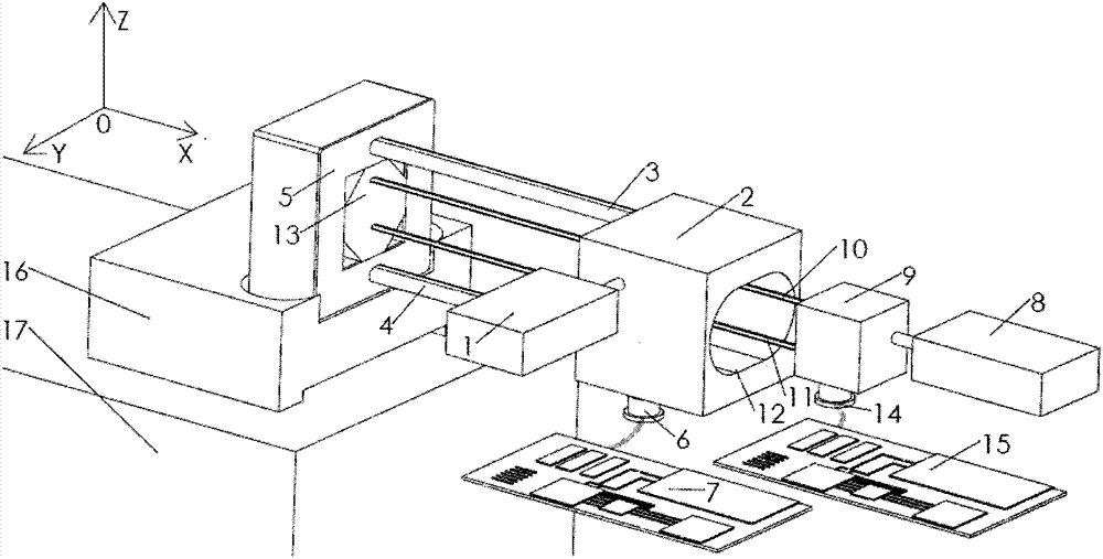
[0018] An angular displacement laser interferometer calibration device based on dual standard optical axes, including a standard laser interferometer laser 1 and a receiver 6 configured at a position that can receive interference signals corresponding to parallel standard measurement beams 3 and 4, the wire connects the receiver 6 is connected to the signal processing system 7 of the standard laser interferometer; the output optical path of the standard laser interferometer laser 1 is provided with an intermediate through hole 12 that allows the calibrated laser interferometer measurement beams 10, 11 to pass through the two-axis hollow standard laser interference Mirror group 2; one side of the two-axis hollow standard laser interference mirror group 2 is equipped with a guide rail 17, and the moving table 16 is mounted on the guid...


PUM


Abstract

The invention provides an angular displacement laser interferometer calibration method and an angular displacement laser interferometer calibration device based on two standard optical axes, and belongs to the technical field of laser measurement. Two measuring light beams of a laser interferometer to be calibrated pass through a middle through hole of a two-axis hollow laser interference mirror group, and are parallelly arranged in the center position of two parallel standard measuring light beams; in a line segment region formed by the two standard measuring light beams at the plane projection points, the differences of environment interference degrees of the two standard measuring light beams and the two measuring light beams of the laser interferometer to be calibrated are very small, and the air refractive index average value of the standard measuring light beams is approximate to the air refractive index value of the measuring light beams of the laser interferometer to be calibrated.

Description

technical field [0001] The invention belongs to the technical field of laser measurement, and mainly relates to a laser interferometer calibration method and device. Background technique [0002] Angular displacement laser interferometer is a standard measurement technology with high precision. It is widely used in precision and ultra-precision machining, microelectronic equipment, nanotechnology industrial equipment and national defense equipment. It can be used for micro-displacement components, mobile platforms and lithography Monitoring of machine angle changes. The angular displacement laser interferometer can provide high measurement accuracy, and can dynamically measure the relative swing angle in motion, which is a unique advantage different from other instruments. In order to ensure the accuracy of the angular displacement laser interferometer measurement, the Calibration of the displacement laser interferometer is very important. The realization of the angular di...

Claims


Application Information

Patent Timeline
Patent Type & Authority Applications(China)
IPC IPC(8): G01B9/02G01B11/26
Inventor 胡鹏程谭久彬
Owner HARBIN INST OF TECH
Why Eureka
Try Eureka