High-precision residual static correction method with combination between space variation and a plurality of time windows

A high-precision, static correction technology, applied in the field of petroleum seismic exploration, to achieve the effect of clear local details, clear results, and elimination of influences

Inactive Publication Date: 2014-01-08
中国石油集团西北地质研究所有限公司
View PDF4 Cites 15 Cited by
  • Summary
  • Abstract
  • Description
  • Claims
  • Application Information

AI Technical Summary

Problems solved by technology

[0005] The purpose of the present invention is to overcome the remaining static correction distortion caused by the inaccurate dynamic correction speed in double-complex and low signal-to-noise ratio areas, and to avoid the disadvantages of non-surface consistent algorithms such as Trim that are prone to false structures, and to provide a space Variable-multi-time window fusion high-precision residual static correction method; this method can not only eliminate the influence of velocity error on the calculation of residual static correction, but also effectively solve the problem of non-surface consistent static correction to a certain extent

Method used

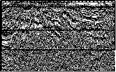
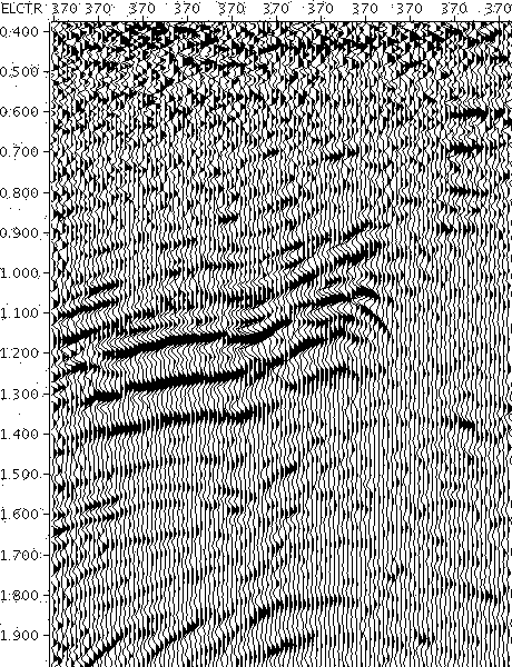

Image

  • High-precision residual static correction method with combination between space variation and a plurality of time windows
  • High-precision residual static correction method with combination between space variation and a plurality of time windows
  • High-precision residual static correction method with combination between space variation and a plurality of time windows

Examples


Embodiment Construction

[0023] Below exemplifies method of the present invention to be described in further detail

[0024] Space-variation-multi-time window fusion high-precision residual static correction method; the steps of the method are as follows:

[0025] 1) Obtain accurate basic static correction amount and completely solve the problem of long wavelength;

[0026] 2) Do a good job in improving the signal-to-noise ratio such as pre-stack denoising;

[0027] 3) Carry out three-dimensional macroscopic control of the spatial variation trend of the underground structure in order to determine the selection of the spatial variation time window;

[0028] 4) According to the vertical and horizontal variation trends of the underground structure, determine the number of space-variable time windows and the time range of the space-variable time windows; time window 1: 700-2100ms, time window 2: 200-1000ms, and time window 3: 200—1500ms;

[0029] 5) According to the time range of the previously select...


PUM


Abstract

Provided is a high-precision residual static correction method with combination between space variation and a plurality of time windows. The high-precision residual static correction method with combination between space variation and the time windows comprises the steps of (1) obtaining an accurate basic static correction value, solving the problem of the long wavelength, (2) carrying out pre-stack noise removal to increase the signal to noise ratio, (3) carrying out three-dimensional space control on the space of an underground structure to select and determine space-variant time windows, (4) determining the number of the space-variant time windows and the time range according to the variation trend of the underground structure, (5) carrying out calculation to obtain models and residual static correction values through different space-variant time windows according to the selected time range, (6) resolving the residual static correction value, carrying out three-dimensional space splicing on the residual static correction value according to the stacking effect calculated through different space-variant time windows, and (7) resolving the spliced residual static correction value into respective shot points, geophones and a CMP residual static correction value. The integral signal to noise ratio of a stacked section obtained through the high-precision residual static correction method with combination between space variation and the time windows is increased, The whole appearance of the section can be clearer compared with the result obtained through conventional residual static correction of a single time window, local details can be clearer, and the high-precision residual static correction method with combination between space variation and the time windows is especially feasible and effective in a double-complexity area and an area with a low signal to noise ratio.

Description

technical field [0001] The invention belongs to the technical field of petroleum seismic exploration, technical processing and interpretation of seismic data, and specifically relates to a high-precision three-dimensional static correction based on variogram fitting and reconstruction, a space-variant-multi-time window fusion high-precision residual static correction method. Background technique [0002] In the prior art, after the basic static correction, it is generally necessary to further eliminate the influence of the short-wavelength static correction through residual static correction processing. At present, there are mainly three types of residual static correction schemes: one is the surface consistent residual static correction method based on the correlation class, which picks up the time-shift of the seismic trace through correlation and other schemes, and inverts the picked-up time-shift to obtain the shot, The calculation efficiency of this method is relatively...

Claims


Application Information

Patent Timeline
Patent Type & Authority Applications(China)
IPC IPC(8): G01V1/36
Inventor 王小卫王宇超苏勤徐新荣王述江雍运动王艳香
Owner 中国石油集团西北地质研究所有限公司
Why Eureka
Try Eureka