A sodium-sulfur battery

A sodium-sulfur battery and electrolyte technology, applied in the field of chemical energy storage, can solve the problems of active material leakage, time-consuming and laborious, and easy damage of the electrolyte ceramic tube 4, and achieve the effect of reducing requirements and protecting the bottom

Active Publication Date: 2016-01-20
上海电气企业发展有限公司
View PDF4 Cites 0 Cited by
  • Summary
  • Abstract
  • Description
  • Claims
  • Application Information

AI Technical Summary

Problems solved by technology

Once the electrolyte ceramic tube 4 has microcracks or breaks, the direct contact between sodium and sulfur will cause a violent reaction, and the temperature can reach up to 2000°C, instantly melting all the components in the sodium-sulfur battery, resulting in the leakage of active materials
The safety protection structure of the existing sodium-sulfur battery mainly adopts a safety tube 8 that is socketed between the electrolyte ceramic tube 4 and the sodium storage tube 9 and has a large expansion coefficient with the electrolyte ceramic tube 4. The safety tube 8 is usually made of aluminum or aluminum alloy. , the radial gap 401 between the safety tube 8 and the inner wall of the electrolyte ceramic tube 4, the width of the radial gap 401 is controlled at 100 microns, when the electrolyte ceramic tube 4 is damaged, the safety tube 8 axially expands to be close to the electrolyte ceramic tube 4 inner wall, and give the inner wall of the bottom of the electrolytic ceramic tube 4 a pressure, which is greater than the pressure on the outer wall of the bottom of the electrolytic ceramic tube 4, and the radial gap 401 between the safety tube 8 and the electrolytic ceramic tube 4 also follows the pressure of the safety tube 8 The radial expansion of the closed, sodium and sulfur can not access
This protection method has high requirements on the verticality of the electrolyte ceramic tube 4 and the roundness of the bottom of the electrolyte ceramic tube 4, so processing the electrolyte ceramic tube 4 is time-consuming and laborious, and at the same time, the electrolyte ceramic tube 4 is easily damaged during use.

Method used


Image

  • A sodium-sulfur battery
  • A sodium-sulfur battery
  • A sodium-sulfur battery

Examples


Embodiment Construction

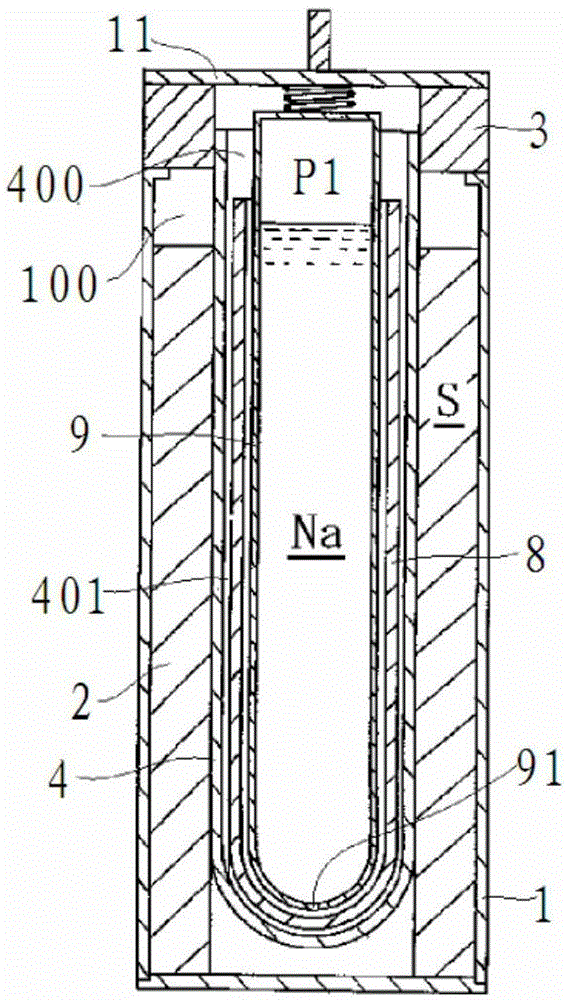
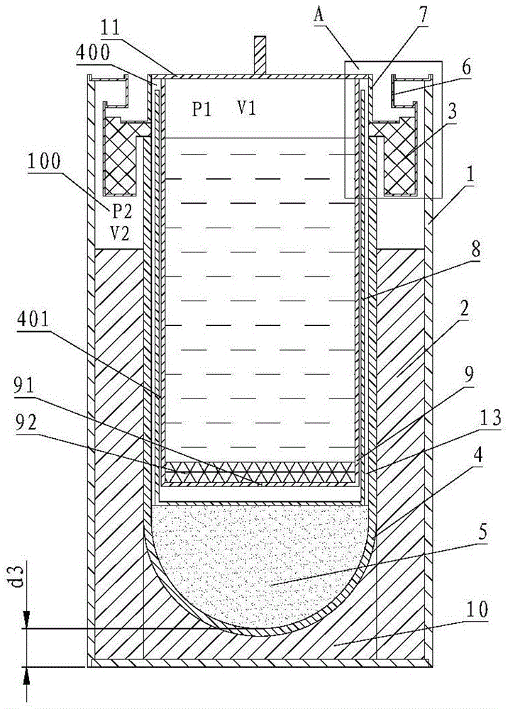
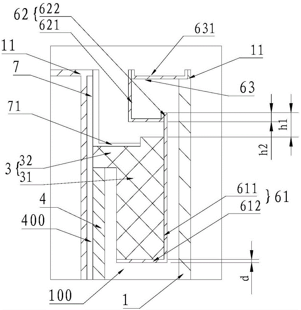
[0023] see figure 2 and image 3 In order to better understand the technical solution of the present invention, the inventors of the present invention will describe in detail below through specific embodiments in conjunction with the accompanying drawings:

[0024] see figure 2 and image 3 , a sodium-sulfur battery of the present invention, including a casing 1 , an electrolyte ceramic tube 4 , a safety tube 8 and a sodium storage tube 9 , which are socketed from outside to inside. The radial inner side of the electrolyte ceramic tube 4 is the negative electrode chamber 400 of the sodium-sulfur battery. Between the electrolyte ceramic tube 4 and the casing 1 is the positive electrode chamber 100 of the sodium-sulfur battery. Therefore, both the safety tube 8 and the sodium storage tube 9 are located in the negative electrode chamber 400 . The top of the sodium storage tube 9 is closed by welding with the negative electrode sealing cover 11 . The top of the sodium stor...


PUM

PropertyMeasurementUnit
porosityaaaaaaaaaa

Abstract

The invention discloses a sodium-sulfur battery in the field of chemical energy storage, comprising a casing and an electrolyte ceramic tube sleeved in the casing; a positive electrode chamber is formed between the casing and the electrolyte ceramic tube radially, and a negative electrode chamber is formed radially inside the electrolyte ceramic tube , the positive chamber is filled with porous conductive fiber felt, the top surface of the electrolyte ceramic tube is provided with a radially outwardly protruding ceramic insulating ring, and a positive sealing device is provided between the ceramic insulating ring and the shell to seal the positive chamber, and the negative chamber is equipped with There is a sodium storage tube and a safety tube sleeved on the outside of the sodium storage tube. The top of the sodium storage tube is closed by the negative electrode sealing cover. A negative electrode sealing ring is provided between the ceramic insulating ring and the negative electrode sealing cover to seal the negative electrode chamber. The outer wall of the safety tube is An insulating and non-wetting buffer layer is provided between the bottom of the electrolyte ceramic tube and the bottom of the inner wall of the electrolyte ceramic tube.

Description

technical field [0001] The invention relates to a sodium-sulfur battery in the field of chemical energy storage. Background technique [0002] Such as figure 1 As shown, the sodium-sulfur battery includes a casing 1 and an electrolyte ceramic tube 4 sleeved in the casing 1 . A positive electrode chamber 100 is formed between the casing 1 and the electrolyte ceramic tube 4 , and the positive electrode chamber 100 is filled with porous conductive fiber mats 2 . A ceramic insulating ring 3 protruding radially outward is provided on the top surface of the electrolyte ceramic tube 4 to seal the positive electrode chamber 100 . The negative electrode chamber 400 is formed inside the electrolyte ceramic tube 4 . The negative electrode chamber 400 is provided with a sodium storage tube 9 and a safety tube 8 sleeved on the outside of the sodium storage tube 9 . The bottom of the sodium storage tube 9 is provided with a through hole 91 , and the top of the sodium storage tube 9 is...

Claims


Application Information

Patent Timeline
Patent Type & Authority Patents(China)
IPC IPC(8): H01M10/39H01M2/02H01M50/10
CPCH01M10/3909H01M50/138Y02E60/10
Inventor 刘宇龚明光茅雁邵偲蔚王国林
Owner 上海电气企业发展有限公司
Why Eureka
Try Eureka