Super capacitor charging control circuit

A charging control and supercapacitor technology, applied in battery circuit devices, circuit devices, current collectors, etc., can solve the problems of complex hardware circuit, high cost, complex control, etc., and achieve high power efficiency, simple circuit, and high power efficiency. Effect

Active Publication Date: 2014-01-08
康威通信技术股份有限公司
View PDF5 Cites 11 Cited by
  • Summary
  • Abstract
  • Description
  • Claims
  • Application Information

AI Technical Summary

Problems solved by technology

[0004] The above-mentioned common charging control circuit has the following problems: 1. It is highly dependent on the reliable operation of the software and hardware of the microcontroller system, the control is complicated, and the r...

Method used


Image

  • Super capacitor charging control circuit

Examples


Embodiment Construction

[0020] The present invention will be further described below in conjunction with the accompanying drawings and embodiments.

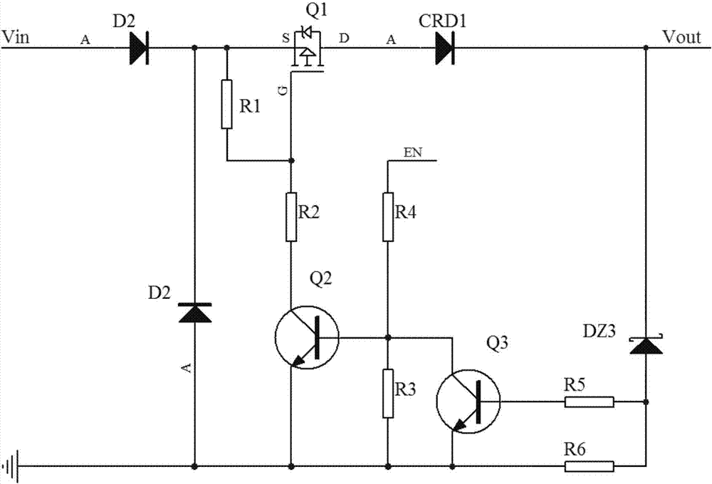
[0021] Such as figure 1 As shown, a supercapacitor charging control circuit includes an input anti-reverse connection circuit, a switch control circuit, a charging constant current circuit, and a charging voltage detection circuit.

[0022] The input anti-reverse connection circuit is composed of a diode D1 and a diode D2. The input DC voltage Vin is firstly connected to the charging switch control circuit of the subsequent stage through the input anti-reverse connection circuit. Regardless of whether the input DC voltage Vin is input through the anode of the diode D1 or through the anode of the diode D2, it can ensure that it is correctly input to the source S of the field effect transistor Q1 of the charging switch control circuit of the subsequent stage, which plays a role of reverse connection protection.

[0023] The switch control circuit includ...


PUM


Abstract

The invention provides a super capacitor charging control circuit which comprises an input reverse connection prevention circuit, a switch control circuit, a charging constant current circuit and a charging voltage detection circuit, wherein the input reverse connection prevention circuit is connected with the switch control circuit in series; the switch control circuit is connected with the charging voltage detection circuit in series; one end of the charging constant current circuit is connected with the switch control circuit, and the other end of the charging constant current circuit is connected with an output end of the charging voltage detection circuit. The constant current action mechanism and the voltage limiting action mechanism of the super capacitor charging control circuit are decided by the inherent physical characteristics of a constant current diode and a voltage stabilizing diode and are independent of the normal operation of a single-chip microcomputer or the program thereof; the super capacitor charging control circuit does not adopt a linear direct current (DC) voltage stabilizing circuit of the common charging control circuit, thus being free from electric energy loss caused by a linear adjusting component, and realizing higher power supply efficiency.

Description

technical field [0001] The invention relates to a super capacitor charging control circuit, in particular to a capacitor charging control circuit capable of effectively limiting charging current and charging upper limit voltage. Background technique [0002] Supercapacitors have large capacity, low withstand voltage, and can be charged and discharged at high currents. They are often deployed in places where power is scarce, and are used to store energy to drive high-current, short-term loads. The energy storage application of supercapacitors usually requires constant low current charging for a long time. When the voltage reaches the designed upper limit voltage, the control circuit can automatically shut down the charging circuit and stop charging to prevent supercapacitors from being overcharged and damaged. [0003] To achieve the above control requirements, the traditional method is: the input power supply voltage first passes through a linear regulated power supply contr...

Claims


Application Information

Patent Timeline
IPC IPC(8): H02J7/00
Inventor 杨震威李长忠
Owner 康威通信技术股份有限公司
Why Eureka
Try Eureka