
Separation device for removing sludge in oily wastewater

A separation device and sludge technology, applied in the direction of flotation water/sewage treatment, flocculation/sedimentation water/sewage treatment, etc., can solve the problems of large dosage of chemicals, low degree of automation, inability to recycle resources, etc., and achieve effective Separation, high degree of automation, avoiding the effect of sludge clogging

Inactive Publication Date: 2014-01-15
SICHUAN WEST POLY XIN CHEM PACKING
View PDF0 Cites 3 Cited by
  • Summary
  • Abstract
  • Description
  • Claims
  • Application Information

AI Technical Summary

Problems solved by technology

[0003] The invention provides a separation device for removing sludge in oily wastewater, which solves the problems of large dosage of chemicals, low degree of automation, and inability to recycle resources in the previous sludge removal process in oily wastewater

Method used


Image

  • Separation device for removing sludge in oily wastewater

Examples


Embodiment

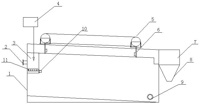
[0017] Such as figure 1 As shown, this embodiment includes a separation chamber 1 and a reaction chamber 3 and a mud scraping device arranged on the separation chamber 1 .

[0018] The separation chamber 1 of this embodiment is a tank body with a sealing cover, and the mud scraping device is located on the sealing cover.

[0019] The separation chamber 1 of this embodiment is provided with a water inlet 2 and a water outlet 9 , the water inlet 2 communicates with the reaction chamber 3 , and a dosing device 4 is arranged above the reaction chamber 3 .

[0020] The separation chamber 1 of this embodiment is also provided with a collection tank 7 , and a mud bucket 8 is provided below the collection tank 7 .

[0021] The mud scraping device in this embodiment includes a conveying device 5 and at least one scraper 6 arranged on the conveying device 5 , and one end of the conveying device 5 close to the water inlet 2 is higher than the other end.

[0022] The reaction chamber 3 ...


PUM


Abstract

The invention discloses an impurity removal device for removing suspended substances in oily sewage, which comprises an impurity removal groove (1) and an impurity removal structure, wherein the impurity removal groove (1) is provided with a water inlet pipe (8) and a water outlet (11); the impurity removal structure comprises a disk (2) and a motor (3); the disk (2) is linked with the motor (3); the disk (2) is fixed to the side wall of the impurity removal groove (1) through a rotating shaft; the motor (3) is fixed to a support table (4) on the lateral side of the impurity removal groove (1); the side wall on which the disk (2) is positioned is provided with an open hole (6); the open hole (6) is provided with an oblique scraper (7) and a guide groove (9); a collecting groove (10) is arranged right below the tail end of the guide groove (9); and a propeller (5) is also arranged in the impurity removal groove (1). By adopting the structure, the impurity removal device is simpler in structure and convenient for operation, and the suspended substances can be thoroughly removed more easily, thereby further enhancing the impurity removal quality.

Description

technical field [0001] The invention relates to the field of wastewater treatment, in particular to a separation device for removing sludge in oily wastewater. Background technique [0002] With the development of industry, more and more high-concentration organic wastewater is produced, causing serious pollution to the environment. In the existing wastewater treatment process, most of the treatment processes do not have a treatment device for high-concentration oily wastewater, but directly mix high-concentration oily wastewater into low-concentration wastewater, which not only increases the amount of chemicals used, but also increases the processing time. Difficulty, the sludge in the wastewater cannot be effectively removed. At the same time, the automation of the whole device is low, and the treated water cannot meet the standard stably, causing the COD of the discharged wastewater to exceed the standard, and it is difficult to recycle and separate the wastewater after a...

Claims


Application Information

Patent Timeline
Patent Type & Authority Applications(China)
IPC IPC(8): C02F1/52C02F1/24
Inventor 马凡江
Owner SICHUAN WEST POLY XIN CHEM PACKING
Learn More