
Ultrasound array imaging method
A technology of ultrasonic array and imaging method, which is applied in the direction of material analysis, measurement device, and instrument using sonic/ultrasonic/infrasonic waves, can solve problems such as serious noise, and achieve improved imaging results, improved detection performance, and improved signal-to-noise ratio. Effect
- Summary
- Abstract
- Description
- Claims
- Application Information
AI Technical Summary
Problems solved by technology
Method used
Image

Examples
Embodiment Construction
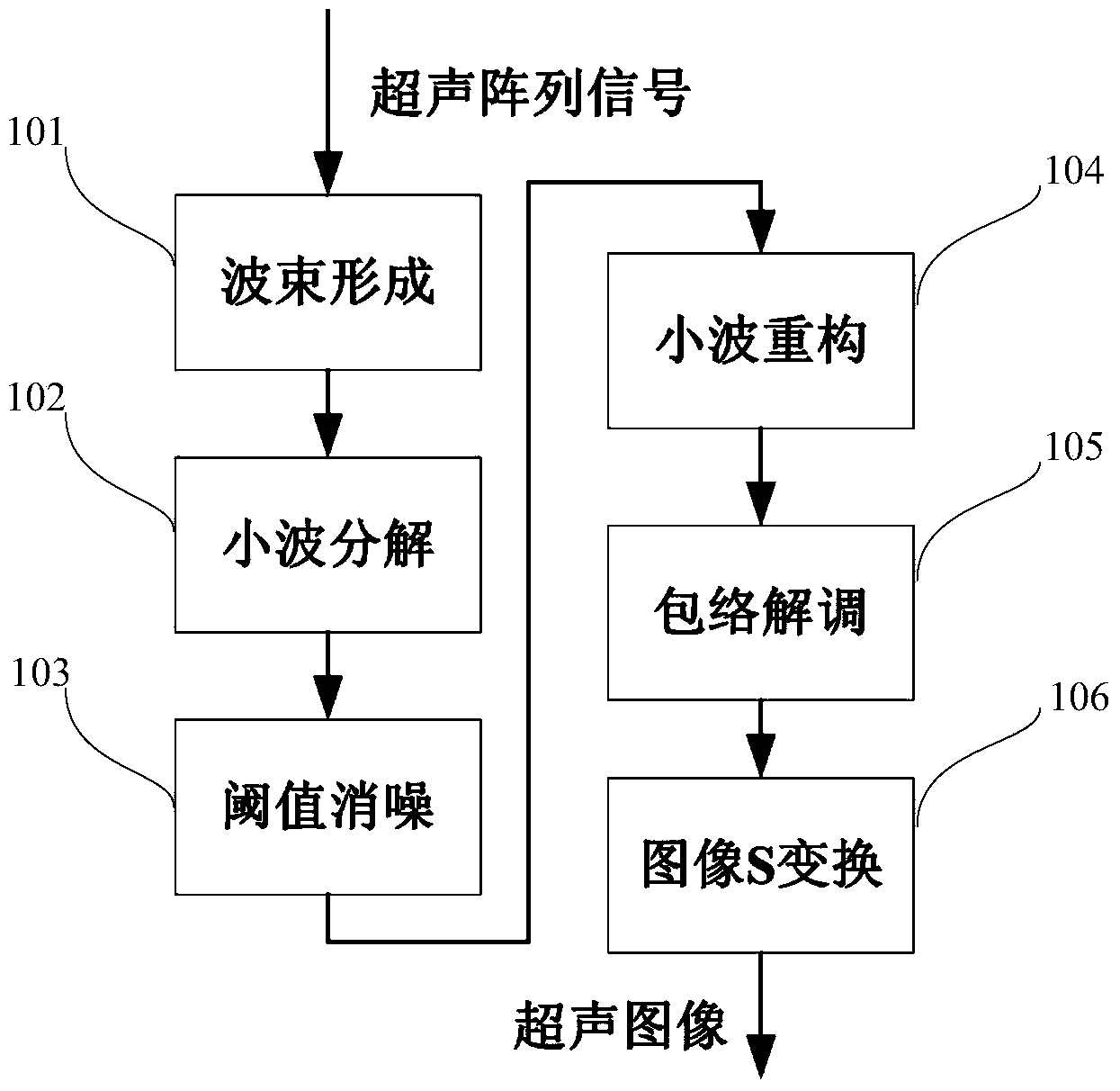
[0017] The technical solutions of the present invention will be further described in detail below through the accompanying drawings and embodiments.
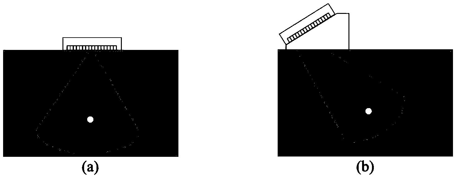
[0018] Ultrasonic array imaging technology is a method of non-destructive testing of components in the industry based on ultrasonic array transducers using ultrasonic longitudinal waves or transverse waves. like figure 2 As shown, the schematic diagrams of scanning the test block by using the ultrasonic array longitudinal wave and generating the shear wave through the wedge block are respectively given. figure 2 (a) By controlling the delay of different array elements, the angle of the incident longitudinal wave is changed to achieve the purpose of imaging the fan-shaped area. This method is called B-mode imaging. figure 2 (b) Control the delay of different array elements, and make the incident longitudinal wave obliquely incident on the part along the interior of the wedge, so as to achieve the purpose of imaging the fan-sh...
PUM
 Abstract
Description
Claims
Application Information