Multilayer scintillation crystal and PET prober

A scintillation crystal and detector technology, applied in the field of positron emission tomography imaging equipment, can solve the problems of time-consuming and labor-intensive acquisition of reference data, and the inability of mass production of detectors

Active Publication Date: 2014-01-15
RAYCAN TECH CO LTD SU ZHOU
View PDF8 Cites 10 Cited by
  • Summary
  • Abstract
  • Description
  • Claims
  • Application Information

AI Technical Summary

Problems solved by technology

The acquisition of reference data is time-consuming and laborious, which also determines that this kind of detector cannot be mass-produced, and it is difficult to apply it to the actual PET system

Method used


Image

  • Multilayer scintillation crystal and PET prober
  • Multilayer scintillation crystal and PET prober
  • Multilayer scintillation crystal and PET prober

Examples


Embodiment 1

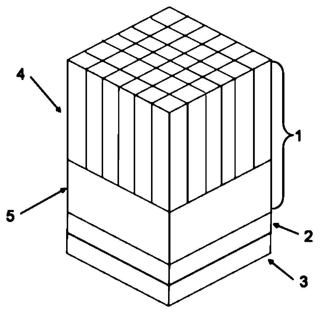
[0043] Such as figure 1 As shown, the PET detector includes a multilayer scintillation crystal 1 , a photodetector system 2 and an algorithm system 3 . Among them, the multi-layer scintillation crystal 1 is composed of two layers of scintillation crystals, the top layer of scintillation crystal 4 is an array scintillation crystal, and the bottom layer of scintillation crystal 5 is a continuous scintillation crystal; the connected surfaces of the two layers of scintillation crystals are coupled together by optical glue. The scintillation crystal 4 on the top layer is in the shape of a cube, which is composed of 6×6 scintillation crystal strips of the same size spliced ​​on the horizontal plane. The bottom surface of the underlying scintillation crystal 5 is directly coupled with the photodetector system 2 . The photodetector system 2 is composed of 4×4 SiPMs. The scintillation crystal 5 on the bottom layer has a height of 1 mm, and the scintillation crystal 4 on the top layer...

Embodiment 2

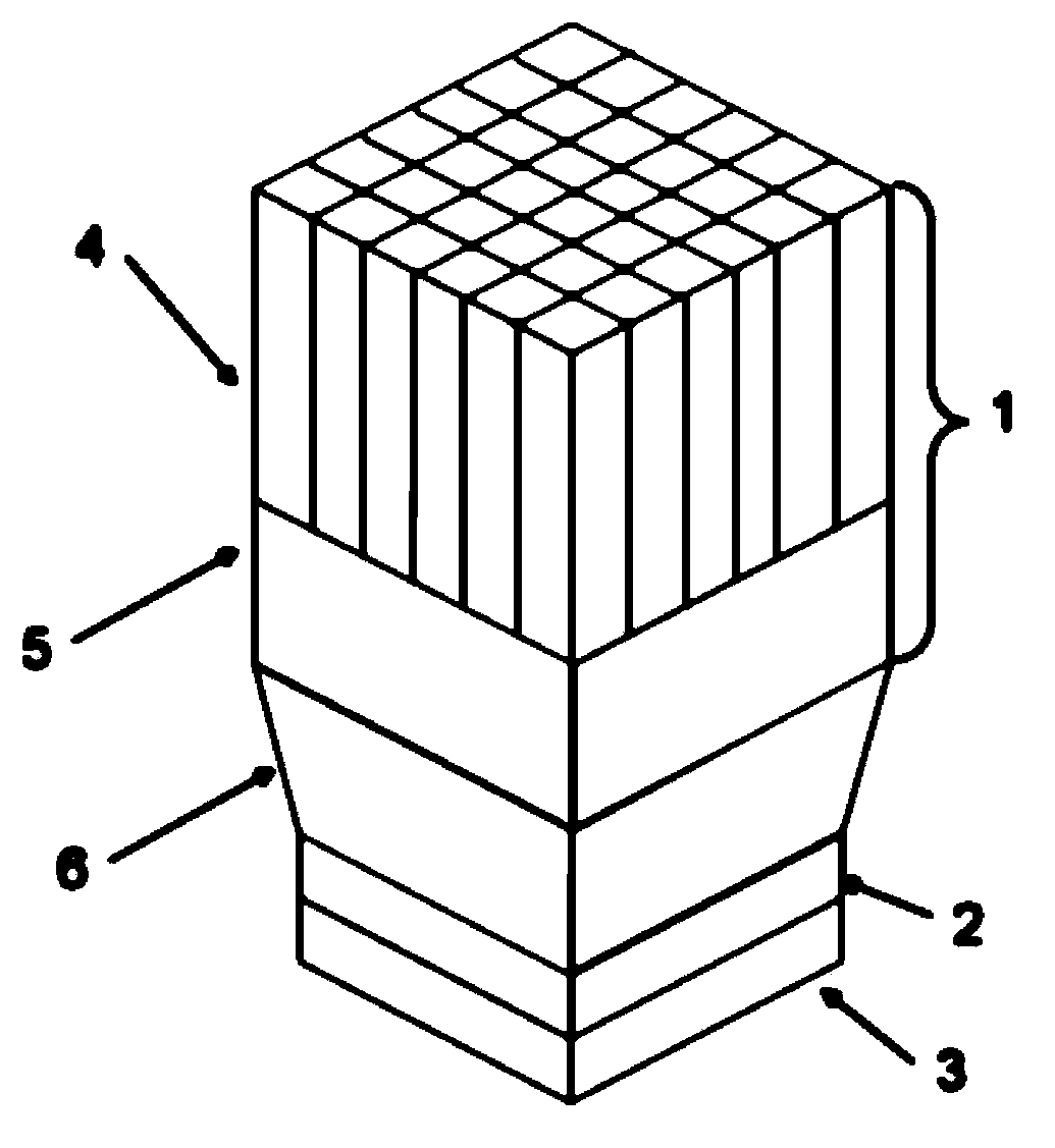
[0045] Such as figure 2 As shown, the PET detector includes a multilayer scintillation crystal 1, a photodetector system 2 and an algorithm system 3, wherein the multilayer scintillation crystal 1 is composed of two layers of scintillation crystals, the top layer scintillation crystal 4 is an array scintillation crystal, and the bottom layer scintillation crystal 5 It is a continuous scintillation crystal; the connected surfaces of two layers of scintillation crystals are coupled together by optical glue and have exactly the same shape and size. The scintillation crystal 4 on the top layer is in the shape of a cube, which is composed of 6×6 scintillation crystal strips of the same size spliced ​​on the horizontal plane. The bottom surface of the underlying scintillation crystal 5 is coupled with the photodetector system 2 through the light guide 6 . The photodetector system 2 is composed of 4×4 SiPMs. The scintillation crystal 5 on the bottom layer has a height of 1 mm, and...

Embodiment 3

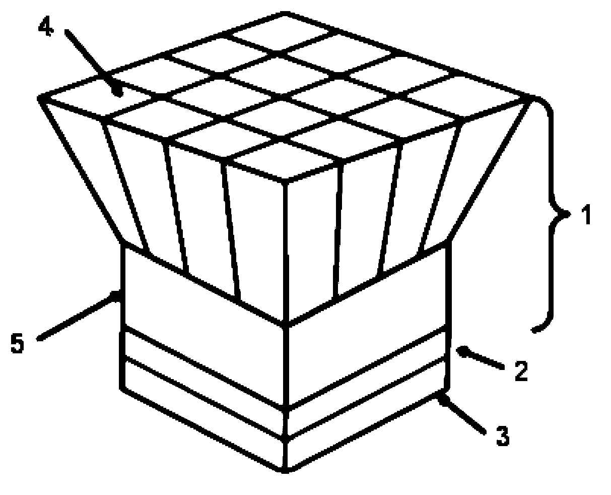
[0047] Such as image 3 As shown, the PET detector includes a multilayer scintillation crystal 1, a photodetector system 2 and an algorithm system 3, wherein the multilayer scintillation crystal 1 is composed of two layers of scintillation crystals, the top layer scintillation crystal 4 is an array scintillation crystal, and the bottom layer scintillation crystal 5 It is a continuous scintillation crystal; the connected surfaces of two layers of scintillation crystals are coupled together by optical glue. The appearance shape of the scintillation crystals 4 on the top layer is a truncated cone. The top surface and the bottom surface of the array scintillation crystals are parallel to each other, and are composed of 4×4 scintillation crystal strips spliced ​​on the horizontal plane. The bottom surface of the underlying scintillation crystal 5 is coupled with the photodetector system 2 through optical glue. The scintillation crystal 5 on the bottom layer has a height of 1 mm, a...


PUM


Abstract

A multilayer scintillation crystal comprises n layers of array scintillation crystal bodies and m layers of continuous scintillation crystal bodies, wherein the interiors of the continuous scintillation crystal bodies are not cut, n and m are both integers greater than or equal to one, and the sum of n and m is smaller than or equal to ten; the array scintillation crystal bodies are formed by arranging long-strip-type scintillation crystal strips in the width direction and the length direction; the array scintillation crystal bodies and the continuous scintillation crystal bodies are sequentially coupled in the height direction of the long-strip-type scintillation crystal strips to form the multilayer scintillation crystal; the bottom layer of the multilayer scintillation crystal is the continuous scintillation crystal bodies. Because the continuous scintillation crystal bodies are additionally arranged between the array scintillation crystal bodies and a photoelectric detector system, the diffusion of flare light photons is facilitated; through the optimized design of the thickness of the continuous scintillation crystal bodies, the distribution of the flare light received by a photoelectric detector device carries richer energy deposition information; a corresponding information extraction algorithm is matched, and the rich energy deposition information is fully utilized so that the energy deposition information of gamma photons in the scintillation crystal can be more accurately obtained. The invention further discloses a PET prober.

Description

technical field [0001] The invention relates to the field of positron emission tomography equipment, in particular to a multilayer scintillation crystal and a PET detector in the positron emission tomography equipment. Background technique [0002] The Positron Emission Tomography (PET) detector is the key device in the PET imaging equipment, and its main function is to obtain the position, time and energy information of each gamma photon energy deposition in the PET event. In the process of designing and implementing a PET imaging system, in order to improve the imaging performance of the system, it is hoped that the positron emission tomography detector used can provide information on the deposition depth (Depth of Interaction, DOI), have high detection efficiency, good Temporal resolution as well as good spatial resolution. [0003] In existing positron emission tomography detectors, the scintillation crystal part is usually a single-layer array scintillation crystal or ...

Claims


Application Information

Patent Timeline
Patent Type & Authority Applications(China)
IPC IPC(8): G01T1/29
Inventor 谢庆国奚道明朱俊王璐瑶
Owner RAYCAN TECH CO LTD SU ZHOU
Why Eureka
Try Eureka