
A displacement sensor simulation circuit

A technology of displacement sensor and simulation circuit, applied in the field of fly-by-wire flight control system test, can solve the problems of difficult to complete the automatic test of failure, high cost, long time, etc., to shorten the construction period, low cost and reduce cost Effect

Inactive Publication Date: 2014-01-15
XIAN AIRCRAFT DESIGN INST OF AVIATION IND OF CHINA
View PDF6 Cites 11 Cited by
  • Summary
  • Abstract
  • Description
  • Claims
  • Application Information

AI Technical Summary

Problems solved by technology

[0006] In the test, the flight control computer needs to collect the signals of these sensors. The construction of the traditional physical environment often takes a long time and costs a lot.
Moreover, it is difficult to complete the construction of faults and automatic testing of specific functions in a physical environment

Method used


Image

  • A displacement sensor simulation circuit
  • A displacement sensor simulation circuit
  • A displacement sensor simulation circuit

Examples


Embodiment Construction

[0014] The specific embodiments of the present invention will be further described below in conjunction with the accompanying drawings.

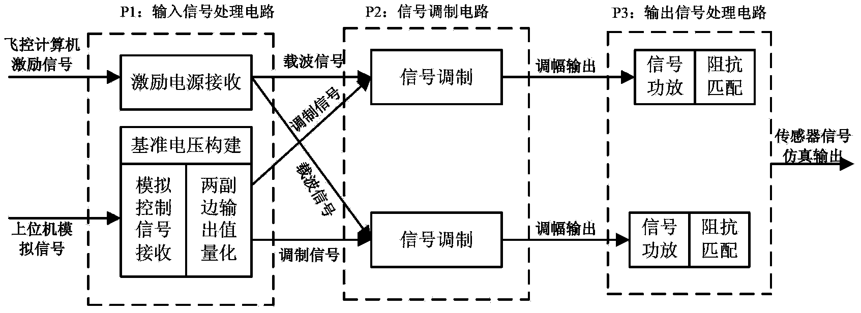
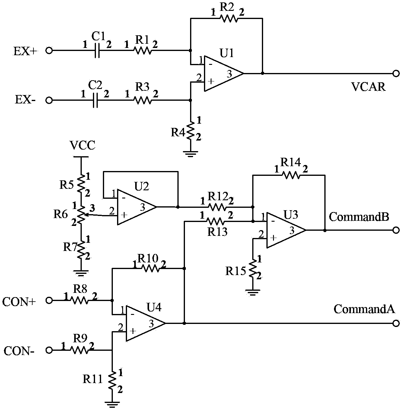
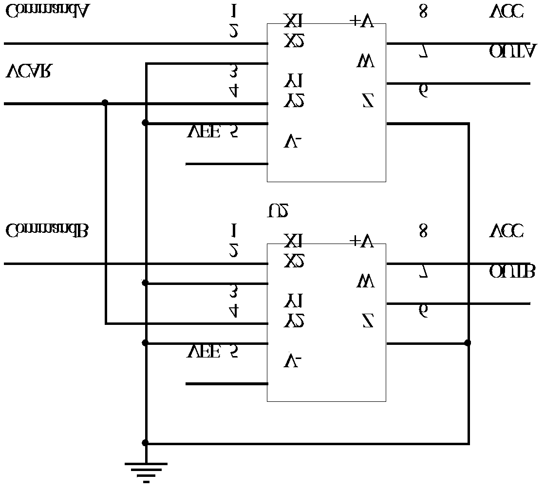
[0015] see figure 1 The principle of realizing simulation by a displacement sensor emulation circuit in the present invention is: the emulation circuit receives an analog output signal from a host computer controlled by software to replace the actual physical manipulation value, and based on the two adjustable corresponding sensors set in the circuit The secondary side sum voltage signal is decomposed into two DC analog signals corresponding to the magnitude of the two secondary side manipulations; then, according to the AC excitation signal from the flight control computer, the two DC analog signals are modulated into two DC analog signals by using the principle of amplitude modulation AC analog signal, these two AC analog signals correspond to the output signal of the simulated sensor; then use the feedback circuit composed of operational ...


PUM


Abstract

The invention belongs to the technical field of telex flight control system tests, and especially relates to a displacement sensor simulation circuit. The displacement sensor simulation circuit of the invention can be divided into three parts which are an input signal processing circuit, a signal modulation circuit, and an output signal processing circuit. The simulation circuit receives simulation output signals, and decomposes the simulation output signals into two paths of direct current simulation signals which are corresponding to two secondary manipulated variables in terms of sizes. The two direct current simulation signals are modulated to two paths of alternating current simulation signals through the utilization of an amplitude modulation principle. A driving capability of the signals is raised through the utilization of a reactive circuit composed of an operational amplifier and a triode, and a transformer is driven to be an output, so that secondary output impedance characteristics of a linear displacement sensor are simulated. The displacement sensor simulation circuit of the invention is simple in design, low in cost, and can simulate the signals of the displacement sensor very well.

Description

technical field [0001] The invention belongs to the field of fly-by-wire flight control system test technology, and in particular relates to a displacement sensor simulation circuit. Background technique [0002] In the aircraft of the fly-by-wire flight control system, the pilot control sensor is the signal source of the manual control of the aircraft, which converts the pilot's control displacement (or control force) of the control stick and pedals into a voltage signal proportional to it, and sends it to into the flight control computer. Fly-by-wire flight control systems or control enhancement systems generally use displacement sensors as the driver's manipulation sensors. Driver manipulation sensors come in two forms: [0003] Linear Variable Differential Transformer (Displacement Transducer, LVDT): Converts linear displacement into a voltage signal. [0004] Rotary Variable Differential Transformer (Angular Displacement Transducer, RVDT): Converts angular displaceme...

Claims


Application Information

Patent Timeline
Patent Type & Authority Applications(China)
IPC IPC(8): G05B17/02
Inventor 杜永良
Owner XIAN AIRCRAFT DESIGN INST OF AVIATION IND OF CHINA
Learn More