Secondary battery

A secondary battery and current collector technology, applied in secondary batteries, battery electrodes, lithium batteries, etc., can solve problems such as battery characteristic degradation, silicon deformation, peeling or micronization, and achieve high capacity effects

Inactive Publication Date: 2014-01-15
SEMICON ENERGY LAB CO LTD
View PDF8 Cites 4 Cited by
  • Summary
  • Abstract
  • Description
  • Claims
  • Application Information

AI Technical Summary

Problems solved by technology

[0009] However, when the amount of occlusion of carrier ions increases, the volume change due to occlusion and release of carrier ions in the charge-discharge cycle is large, the adhesion between the current collector and silicon decreases, and the battery characteristics deteriorate due to charge-discharge.
Furthermore, there is a serious problem that silicon is sometimes deformed or damaged, peeled off or micronized, and as a result, the function as a secondary battery cannot be maintained.
[0013] However, when a heater circuit is installed inside the battery in order to extract the battery performance of the secondary battery in a low-temperature environment as described in Patent Document 1, the structure of the battery element and the structure of the lead-out electrodes become complicated.
In addition, the manufacturing process of the secondary battery becomes complicated
Furthermore, in order to control the heater circuit, a special control unit is required outside the secondary battery, resulting in an increase in cost.
[0014] In addition, when columnar or powdery silicon is used for the negative electrode active material layer described in Patent Document 2 to increase the capacity of the secondary battery, when charging and discharging are repeated over 10 cycles as described in this document , since the carrier ions are occluded and deintercalated by the negative active material, the volume expansion and contraction cannot be avoided
Therefore, the deterioration of the negative electrode active material layer cannot be prevented, and in Patent Document 2, the use of a layer made of black lead for current collection is sought on the premise that silicon of the active material is peeled off from the current collector.
Therefore, it is difficult to maintain the reliability of the battery with the above structure
In addition, in this structure, whether the secondary battery can perform its function in a low temperature environment is not involved

Method used


Image

  • Secondary battery
  • Secondary battery
  • Secondary battery

Examples


Embodiment approach 1

[0042] In this embodiment, an electrolyte and a solvent used for a negative electrode and an electrolytic solution of a secondary battery according to one embodiment of the present invention will be described. In addition, a method for producing the negative electrode will be described.

[0043] (Structure of negative electrode)

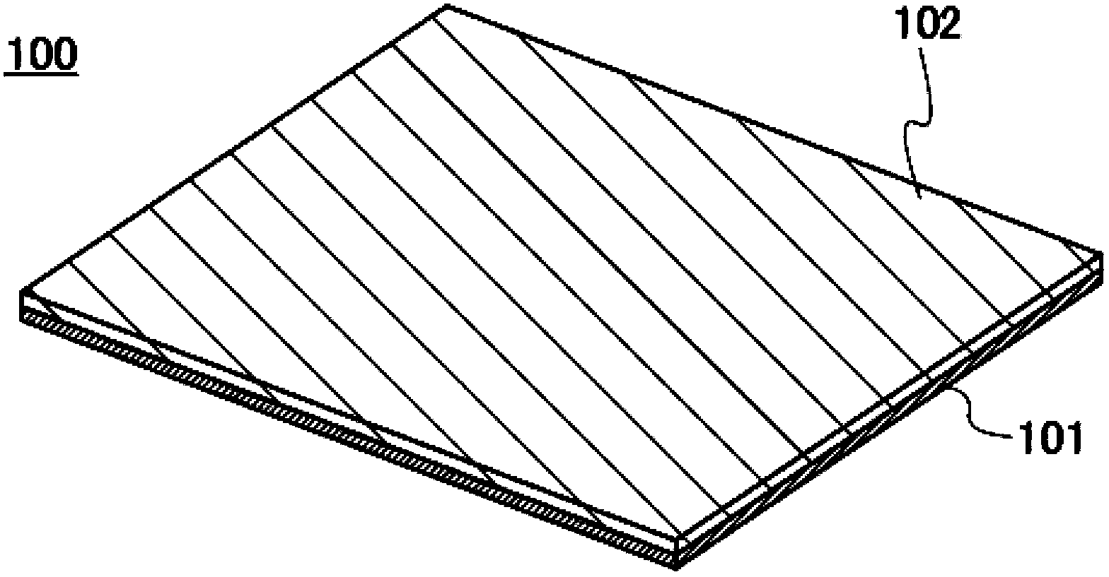
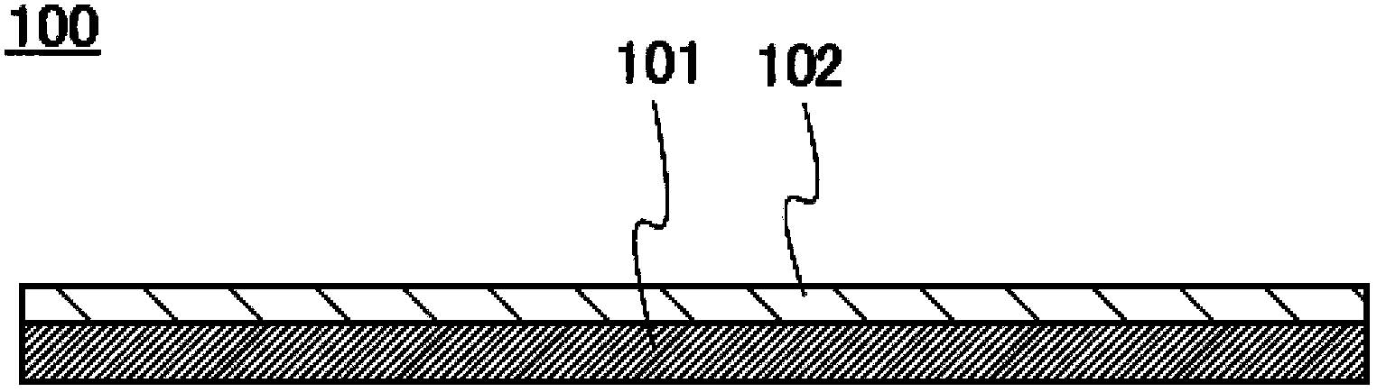
[0044] Figure 1A is a graph looking down on the negative pole, and Figure 1B It is a figure which shows the cross section in the thickness direction of a negative electrode. The negative electrode 100 has a structure in which a negative electrode active material layer 102 is provided on a negative electrode current collector 101 . In addition, although the negative electrode active material layer 102 is provided on only one surface of the negative electrode current collector 101 in the drawings, the negative electrode active material layer 102 may be provided on both surfaces of the negative electrode current collector 101 .

[0045] As the neg...

Embodiment approach 2

[0086] In this embodiment, refer to Figure 2A and 2B as well as Figure 3A and 3B The structure of the secondary battery will be described.

[0087] (Coin type secondary battery)

[0088] Figure 2A This is an external view of a coin-type (single-layer flat type) secondary battery, and partially shows its cross-sectional structure.

[0089] In the coin-type secondary battery 200, a positive electrode can 201 serving as a positive terminal and a negative electrode can 202 serving as a negative terminal are insulated by using a gasket 203 formed of polypropylene or the like. and sealed. The positive electrode 204 is formed of a positive electrode current collector 205 and a positive electrode active material layer 206 provided in contact therewith. In addition, the negative electrode 207 is formed of a negative electrode current collector 208 and a negative electrode active material layer 209 provided in contact therewith. A separator 210 and an electrolyte (not shown) ...

Embodiment approach 3

[0129] A secondary battery according to one aspect of the present invention can be used as a power source for various electronic devices driven by electricity. In particular, the secondary battery according to one aspect of the present invention is suitable for electronic devices that are expected to be used in low-temperature environments such as cold regions.

[0130] Specific examples of electronic equipment using the secondary battery according to one aspect of the present invention include display devices such as televisions and monitors, lighting devices, desktop or notebook personal computers, word processors, playback and storage on DVD (Digital Versatile Disc (Digital Versatile Disc) Image reproduction devices for still images or moving images on recording media such as digital versatile discs), portable CD players, radios, tape recorders, headphones, stereos, desk clocks, wall clocks, cordless telephone handsets, walkie-talkies , portable wireless devices, mobile pho...


PUM

PropertyMeasurementUnit
thicknessaaaaaaaaaa
thicknessaaaaaaaaaa
particle sizeaaaaaaaaaa

Abstract

A secondary battery which can achieve battery performance satisfactorily in a low temperature environment in cold climates or the like is provided. Further, a secondary battery having high capacity even in a low temperature environment in cold climates or the like is provided. A secondary battery includes a positive electrode, a negative electrode, and an electrolyte solution which contains a nonaqueous solvent and an electrolyte. The negative electrode includes a negative electrode active material layer. The negative electrode active material layer contains graphene, a binder, and a negative electrode active material containing a particulate alloy-based material. The nonaqueous solvent contains propylene carbonate and the electrolyte contains lithium perchlorate.

Description

technical field [0001] The present invention relates to a secondary battery. Background technique [0002] In recent years, portable electronic devices such as mobile phones, smartphones, e-book readers (e-books), portable game machines, and the like have spread widely. Accordingly, research and development on secondary batteries typified by lithium secondary batteries, which are driving power sources for these devices, has been actively conducted. In addition, the importance of secondary batteries in various applications is increasing due to increasing interest in global environmental issues and petroleum resource issues, and attention has been paid to hybrid vehicles and electric vehicles. [0003] Among secondary batteries, lithium secondary batteries are widely popular because of their high energy density, and lithium secondary batteries include lithium cobalt oxide (LiCoO 2 ) or lithium iron phosphate (LiFePO 4 ) and other active materials, negative electrodes made o...

Claims


Application Information

Patent Timeline
Patent Type & Authority Applications(China)
IPC IPC(8): H01M4/583H01M4/62H01M10/0568H01M10/0569H01M10/0525
CPCH01M4/621H01M4/625H01M10/0561H01M10/0567H01M2300/002H01M2300/0028H01M4/131H01M4/134H01M4/136H01M4/366H01M4/38H01M4/386H01M4/387H01M4/466H01M4/485H01M4/58H01M10/052H01M10/0568H01M10/0569Y02E60/10H01M4/405
Inventor 荻野清文
Owner SEMICON ENERGY LAB CO LTD
Why Eureka
Try Eureka