Tail gas scrubber and method of use thereof

A tail gas scrubbing and tail gas technology, applied in the direction of separation methods, use of liquid separation agents, chemical instruments and methods, etc., can solve the problems of loss of economic benefits, production reduction, etc., and achieve less process links, reduce water storage, and be easy to implement Effect

Inactive Publication Date: 2015-09-30
SHANGHAI BAOYE CONSTR INDAL FURNACE ENG TECH
View PDF4 Cites 0 Cited by
  • Summary
  • Abstract
  • Description
  • Claims
  • Application Information

AI Technical Summary

Problems solved by technology

When the system fails, the gas inflow can only be cut off, and the production is stopped for maintenance, which directly leads to a reduction in production and loss of economic benefits

Method used


Image

  • Tail gas scrubber and method of use thereof
  • Tail gas scrubber and method of use thereof
  • Tail gas scrubber and method of use thereof

Examples


Embodiment Construction

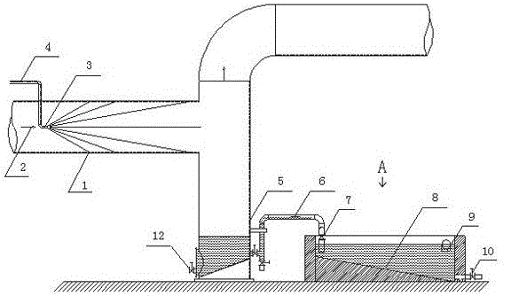
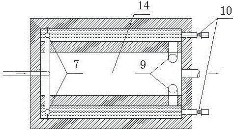
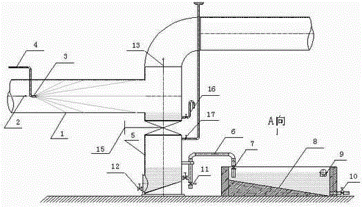
[0034] Such as figure 1 , figure 2 Shown: an exhaust gas cleaning device, which includes an exhaust gas pipeline 1, a fluid spray gun 3, a liquid collector 5, a differential pressure drain pipe 6, a drain valve 7, an inclined plate sedimentation tank 8, a tar filter 9, a sewage valve and a clean water tank 14. The tail gas pipeline 1 communicates with the liquid collector 5, and a fluid spray gun 3 for spraying circulating water 4 is provided in the tail gas pipeline 1. The liquid collector 5 is connected to the inclined plate sedimentation tank through the differential pressure drain pipe 6 and the drain valve 7. 8 connected, the lower part of the liquid collector 5 and the lower end of the inclined plate settling tank 8 are provided with a first sewage valve 12 and a second drain valve 10, and the upper part of the inclined plate settling tank 8 is provided with a tar filter 9, The outlet of the tar filter 9 is provided with a clear water pool 14; the left and right sides ...


PUM


Abstract

The invention relates to a tail gas washing device and a use method of the tail gas washing device. According to the tail gas washing device, a tail gas pipeline is communicated with a liquid collector; the tail gas pipeline is internally provided with a fluid ejection gun for ejecting circulation water; the liquid collector is communicated with an inclined plate settling pond through a differential pressure drain-pipes and drain valves; a tar filter is arranged at the upper part of the inclined plate settling pond; and a clean water pond is arranged at the outlet of the tar filter. According to the use method, primary cleaning water is filled into the clean water pond, the tail gas is washed through the circulation water of the fluid ejection gun, the circulation water flows into the liquid collector, the circulation water is discharged through the different pressure drain-pipes, any drain valve is opened, the circulation water is discharged into the inclined plate settling pond and flows to the other end of the water pond, dust is accumulated at a second pollution discharge valve, and when the circulation water is discharged into the inclined plate settling pond and reaches a certain height, the tar is blocked through the basket type filter, and the circulation water with dust removed and tar blocked flows into a clear water reservoir, is pressurized through a fluid ejection gun pump, and is finally fed into the fluid ejection gun so as to realize cyclic utilization. The tail gas washing device is simple in process and easy to popularize and apply.

Description

technical field [0001] The invention relates to a gas washing and collecting device and its use method, in particular to a tail gas washing device and its use method. Background technique [0002] At present, in the field of chemical industry production, in terms of tail gas recovery and utilization, a combination of scrubbers and large multi-stage sedimentation tanks is often used for secondary purification and dust removal of tail gas. The process is as follows: the gas enters the tower through the lower inlet of the washing tower, and flows upwards; the cold water for washing is sent to the upper water inlet of the washing tower after being pressurized by the pump unit in the pump room, and then jets down. The gas passes through the hump packing support plate installed horizontally, and then filters the tar through the ceramic Raschig ring on the hump plate, washes it with water to cool down, and then passes upward through the wire mesh demister to filter and remove foam ...

Claims


Application Information

Patent Timeline
Patent Type & Authority Patents(China)
IPC IPC(8): B01D47/06B01D36/04
Inventor 刘新洲叶俊初文恩陈文学
Owner SHANGHAI BAOYE CONSTR INDAL FURNACE ENG TECH
Why Eureka
Try Eureka