Underwater vehicle with water jet propulsion technology adopted

An underwater vehicle and water-jet propulsion technology, which is applied in the field of aircraft, can solve the problems of complex water absorption and water pressure structure, lower propulsion efficiency, speed limitation, etc., and achieve improved propulsion efficiency, simple mechanism, and small water resistance Effect

Inactive Publication Date: 2014-01-22
ZHEJIANG UNIV +1
View PDF9 Cites 39 Cited by
  • Summary
  • Abstract
  • Description
  • Claims
  • Application Information

AI Technical Summary

Problems solved by technology

[0004] One is low efficiency
The propeller relies on the high-speed rotation of the impeller to generate a force on the water. The reaction force of the water includes axial force and radial force. The axial force provides propulsion for the aircraft, and the radial force is a useless torque. Useless work reduces propulsion efficiency;
[0005] Second, the speed limit
The disadvantage is that the structure of water absorption and water pressure is complex

Method used


Image

  • Underwater vehicle with water jet propulsion technology adopted
  • Underwater vehicle with water jet propulsion technology adopted
  • Underwater vehicle with water jet propulsion technology adopted

Examples


Embodiment 1

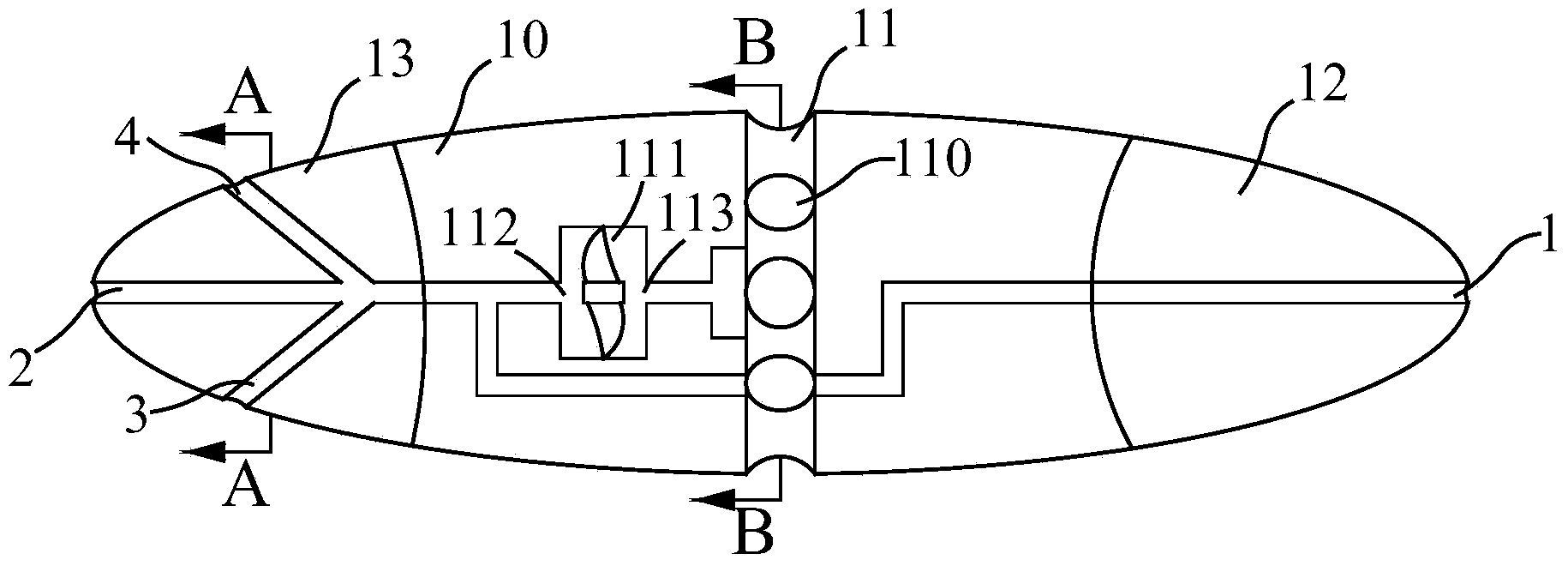
[0025] Embodiment 1, Figure 1 to Figure 6 Provides an underwater vehicle using water jet propulsion technology, including an underwater propulsion device 10 and a control system; the underwater propulsion device 10 includes a tail 13, a water inlet tray 11 and a head 12 arranged in sequence from left to right .

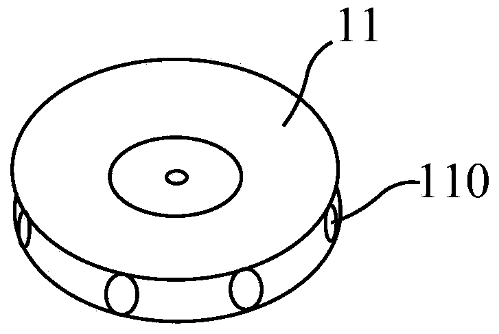
[0026] The water inlet tray 11 is a cylindrical disk made of a polymer composite material. The water inlet tray 110 is provided on the cylindrical surface of the water inlet tray 11. A high-pressure pump 111 is arranged in the water inlet tray 11. The high-pressure pump 111 The water inlet 113 of the pump is connected with the water inlet 110 of the water inlet tray; the water inlet 110 of the water inlet tray has a circumferential opening, and this kind of water inlet with a circumferential opening has the characteristics of large water intake, uniform water intake, and mutual offset of water flow pressure; Due to the use of polymer composite materials, the resista...

Embodiment 2

[0048] Embodiment 2: Another kind of operation mode of the present invention can be formed by controlling the opening and closing of a plurality of switching solenoid valves:

[0049] For example, if the front injection port I1, the rear injection port II2, the lower injection port III3, the left injection port V5 and the right injection port VI6 are closed, the high-pressure water flow will be injected through the upper injection port IV4. At this time, by adjusting Switching the solenoid valve IV 24 and the solenoid valve I 21 on and off can drive the aircraft to dive;

[0050] For example, after closing the rear injection port II2, the upper injection port IV4, the left injection port V5 and the right injection port VI6, the high-pressure water flow will be injected through the lower injection port III3 and the front injection port I1. At this time, by adjusting the switch The opening and closing of the solenoid valve III23 and the switch solenoid valve I21 can drive the ai...


PUM


Abstract

The invention discloses an underwater vehicle with the water jet propulsion technology adopted. The underwater vehicle comprises an underwater propulsion device (10) and a control system. The underwater propulsion device (10) comprises a tail portion (13), a water inlet disk (11) and a head portion (12) which are sequentially arranged from left to right. A jet which is used for providing propulsion power is respectively formed in the tail portion (13) and the head portion (12). The water inlet disk (11) is provided with a water inlet used for sucking water and a high-pressure pump used for converting sucked-in water into high-pressure water flow, and the high-pressure pump is respectively connected with the jets through pipelines. Propulsion power on the jets is provided by the high-pressure water flow obtained from the conversion by the high-pressure pump. The caliber of the water inlet (110) of the water inlet disk is larger than the caliber of the jets. Electromagnetic valves are arranged on the pipelines between the jets and a water outlet (115) of the high-pressure pump. Both the high-pressure pump and a water control device are connected with the control system mutually.

Description

technical field [0001] The invention relates to an aircraft, in particular to an underwater aircraft using water jet propulsion technology. Background technique [0002] In recent years, human beings have continued to explore the ocean, and gradually developed a number of equipment for ocean and lake detection and research. Underwater vehicle is one of the most representative marine detection devices, which are widely used in national defense, coast guard, maritime affairs, customs, nuclear power, hydropower, offshore oil, fishery, sea rescue, pipeline detection and marine scientific research and other fields. According to the nature of its work, underwater vehicles are required to have a stable attitude during the operation and have fast and flexible trajectory and attitude adjustment capabilities. The adjustment and control of the trajectory and attitude of the underwater vehicle needs to have six motion functions: forward, backward, left turn, right turn, rise, and dive....

Claims


Application Information

Patent Timeline
Patent Type & Authority Applications(China)
IPC IPC(8): B63H11/04B63G8/08
Inventor 唐建中余有芳朱煌庆华光徐建国蒋珀
Owner ZHEJIANG UNIV
Why Eureka
Try Eureka