self-propelled dredging vessel

A dredging ship, self-propelled technology, applied in the field of artificial canal dredging equipment, can solve the problems that are not suitable for artificial canal dredging operations, and achieve self-propelled adaptability, simple structure, and low energy consumption

Inactive Publication Date: 2016-05-11
郭丙庄
View PDF6 Cites 1 Cited by
  • Summary
  • Abstract
  • Description
  • Claims
  • Application Information

AI Technical Summary

Problems solved by technology

The above-mentioned existing dredging machinery and equipment have their own specialties, but they are not very suitable for dredging operations in artificial canals of the Yellow River Water Diversion Project or the South-to-North Water Diversion Project

Method used


Image

  • self-propelled dredging vessel
  • self-propelled dredging vessel
  • self-propelled dredging vessel

Examples


Embodiment 1

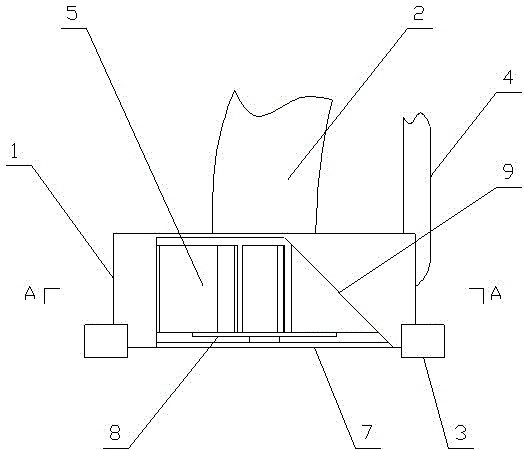
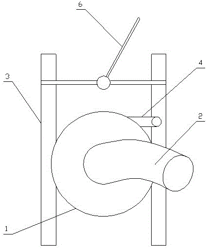
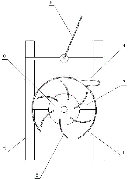
[0032]A self-propelled dredging ship for water channels, comprising a hull 10, power equipment, and a mud delivery mechanism, characterized in that a sludge pump 13 and a water injection pump 11 are arranged on the dredging ship, and the sludge pump and the water injection pump are connected to a self-propelled dredging cutter suction Head 16, the twisted suction head includes a horizontally placed volute 1 that is provided with a hydraulically propelled twisted mud impeller 5, the periphery of the volute is provided with a water inlet pipe 4 that pushes the impeller, and a mud suction port is formed in the center of the impeller, which is integrated with the volute. The mud suction nozzle 2 in the middle of the side is connected, and the mud inlet is set on the side opposite to the water inlet pipe 4 around the volute. The suction head connects the steel cable with the crane lifting arm 15 and forms a fixed connection with the hull.

[0033] The twisted suction head includes ...

Embodiment 2

[0045] A self-propelled dredging ship for water channels, comprising a hull 10, power equipment, and a mud delivery mechanism, characterized in that: a sludge pump 13 and a water injection pump 11 are arranged on the dredging ship, and the sludge pump and the water injection pump are connected to a self-propelled dredging tank via a pipeline. Wringer suction head 16, said twister suction head includes hydraulically propelled mud-cutter impeller 5 arranged in horizontal volute 1, the water inlet pipe 4 that pushes the impeller is arranged on the periphery of the volute and is connected with water injection pump 11, and is formed in the center of the impeller. The mud suction port is connected with the mud suction nozzle in the middle of one side of the volute, and the mud suction nozzle is connected with the sludge pump 13. A mud inlet is provided on the side opposite to the water inlet pipe around the volute, and the mud inlet exposes the impeller. The volute is convenient to s...


PUM


Abstract

The invention discloses manual canal dredging equipment suitable for Yellow River diversion project and south-to-north water diversion project, and particularly a self-propelled dredging ship. The dredging ship is provided with a self-propelled dredging twisting and sucking head in connection with both a dredging pump and a water injection pump; the water injection pump is utilized to provide motive power to the twisting and sucking head, and the dredging pump is utilized to suck sludge, so that dredging of the canal is finished; the twisting and sucking head comprises hydraulically driven sludge twisting impellers which are arranged in a horizontally arranged volute; water inlet pipes for driving the impellers are arranged at the periphery of the volute; a sludge suction hole is formed in the center of the impellers and is communicated with a sludge suction pipe port which is located at the middle part of one side of the volute; one side of the periphery of the volute, which is opposite to the water inlet pipes, is provided with a sludge inlet; the sludge inlet enables the impellers to be exposed out of the volute, so that convenience is brought to the sludge mixing and the sludge suction of the sludge suction hole in the center of the impellers. The self-propelled canal dredging ship has a simple structure, a small number of moving parts, reliable operation, low energy consumption, high efficiency, a self-propelling function, strong adaptability, wide popularization and application foreground, and very remarkable social and economic benefits.

Description

technical field [0001] The invention discloses an artificial canal dredging equipment suitable for water diversion from the Yellow River and south-to-north water diversion projects, in particular to a self-propelled canal dredging ship. Background technique [0002] The history of water diversion from the Yellow River or South-to-North Water Diversion Project is not long, and a large part of the canals are large and medium-sized canals dug manually. There are few dredging machinery and equipment specially used for these canals, and the existing dredging machinery for rivers, lakes and ponds is generally used for their dredging operations. For example, the SLQY-30 amphibious dredger has dual characteristics of single-bucket hydraulic excavation for land and water excavation. The machine uses a flat-bottomed boat as the body, side pontoons increase buoyancy, and is equipped with 4 outriggers with swamp wheels controlled by hydraulic cylinders, which can operate synchronously ...

Claims


Application Information

Patent Timeline
Patent Type & Authority Patents(China)
IPC IPC(8): E02F5/28E02F3/88E02F3/92
Inventor 郭丙庄李学青王炳振张晓宏陈为华张东方李欣杨亚林孙万春
Owner 郭丙庄
Why Eureka
Try Eureka